Flux Converter Part 4

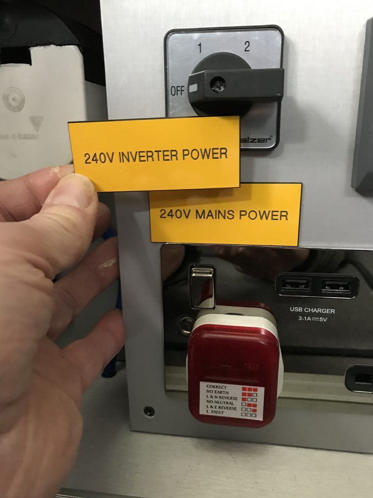
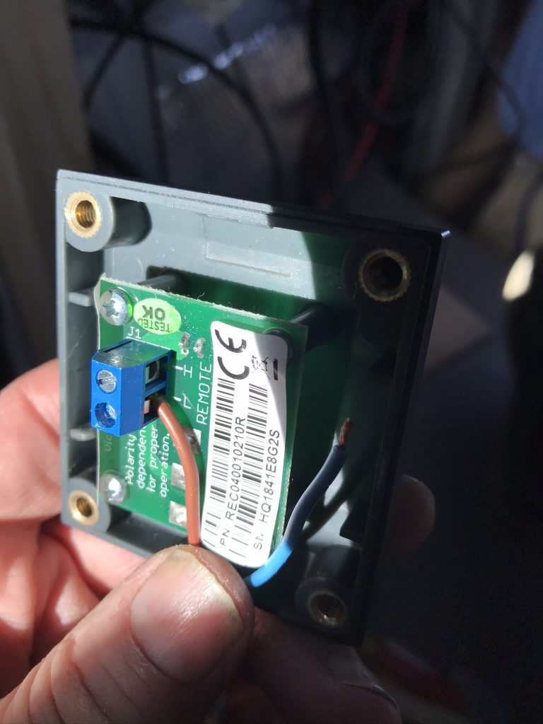
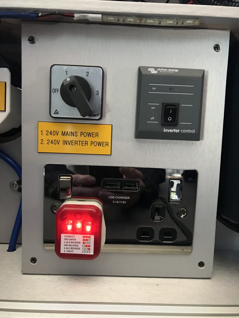
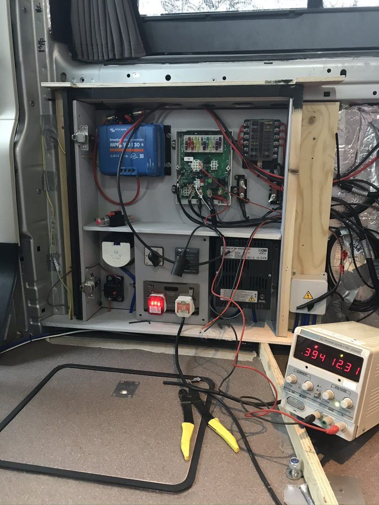
3 Red Lights: The three red lights on the panel below indicates that we now have 240 volts Mains Power (for the first time). The 3 Red Lights are basically a 240 3 Pin UK Plug, when all three lights are displayed it means that the circuit is correctly wired. If any one of the lights is off it means a different thing like incorrect polarity, no earth etc. This plug is not only for testing, it will stay inside the vehicle all the time the van is on the road.

Why keep a Test plug in the Van permanently? This is because in some European Countries (France) they can wire their plugs in reverse to the UK meaning the UK negative is live. The Plug will detect any reverse polarity and explain what it means via the light (one light, two lights etc). I keep a set of reverse polarity Hook-Up Cables in the van at all times. You can buy reverse polarity Hook-Up cables on the internet. To use in Europe, unplug the 3 Pin Power Test Plug from the van and Plug into the European Electricity Feed “BEFORE” plugging any Power into the Van. This Plug will correctly identify the Polarity so that you can use the appropriate Hook Up Cable.

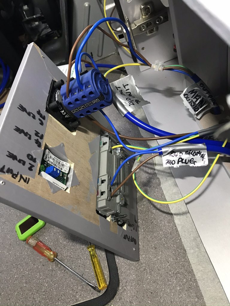
Below: I have connected a Bench Power Supply to my electrics so I can test them and see what current is being drawn.

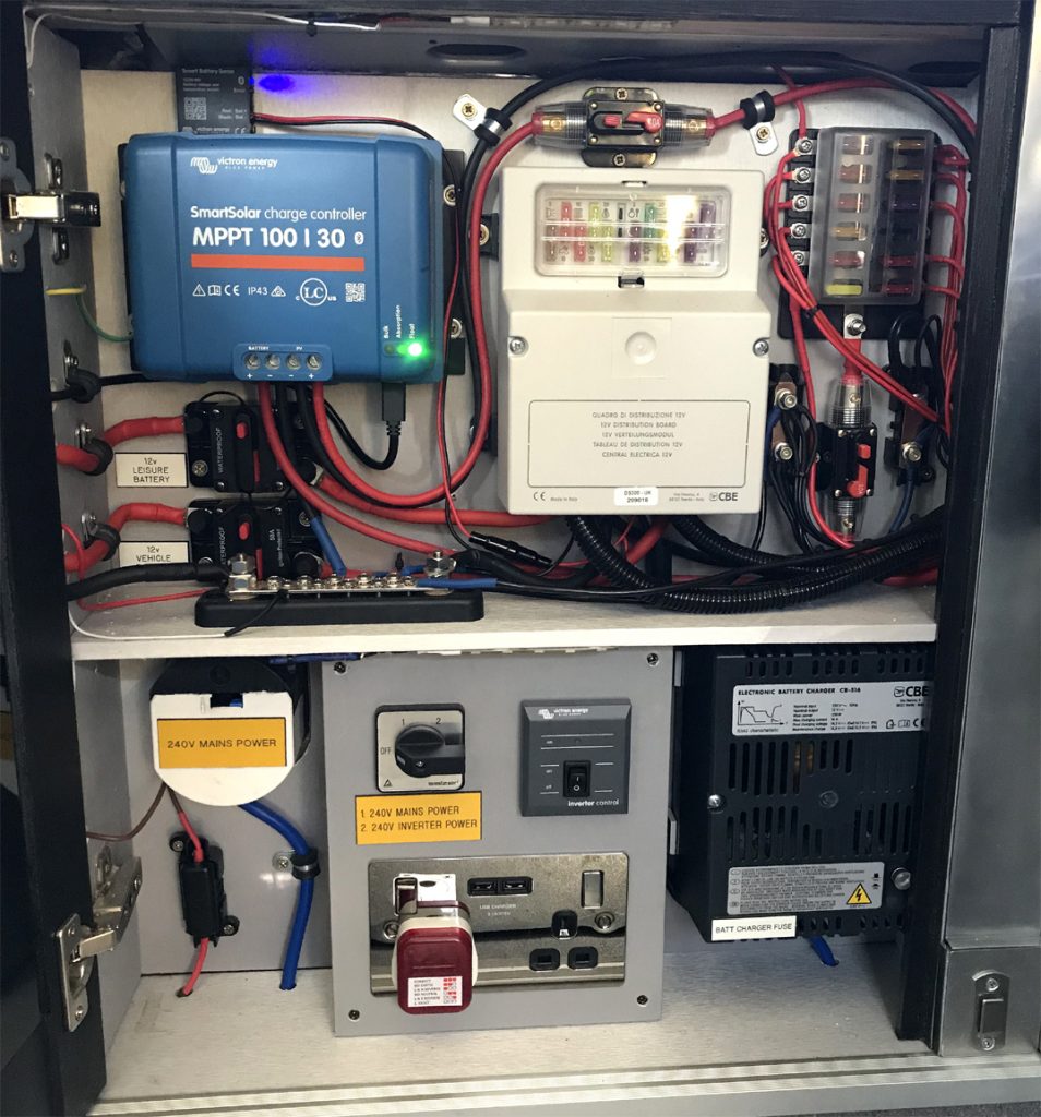
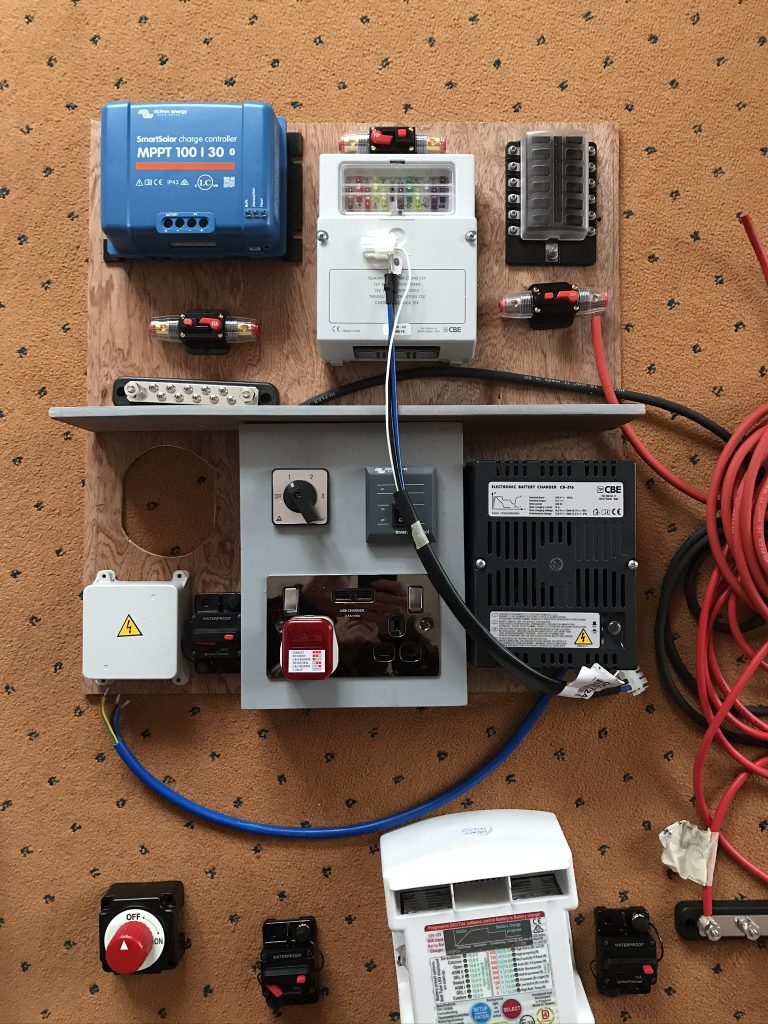
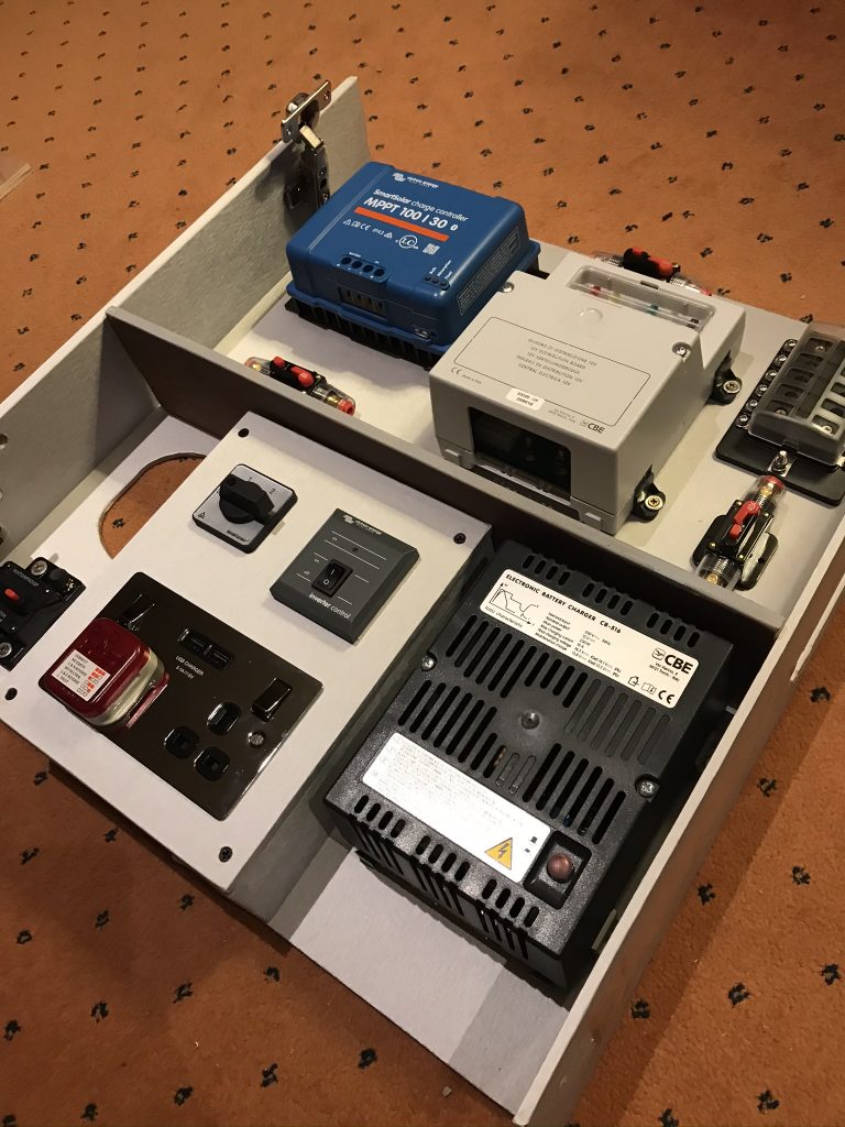
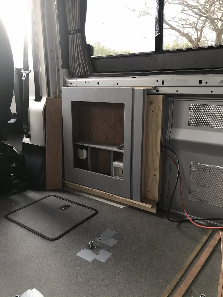
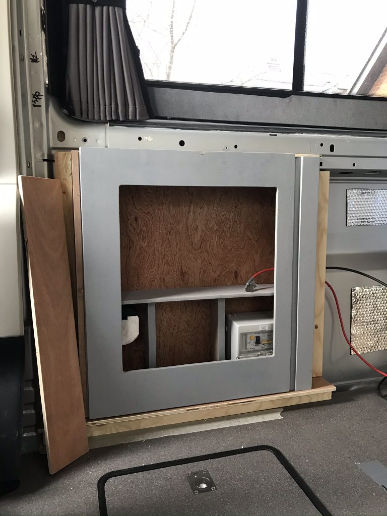
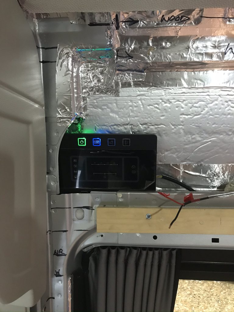
Below: The CBE Control Panel is working for the first time although not all the parts are connected to it yet.

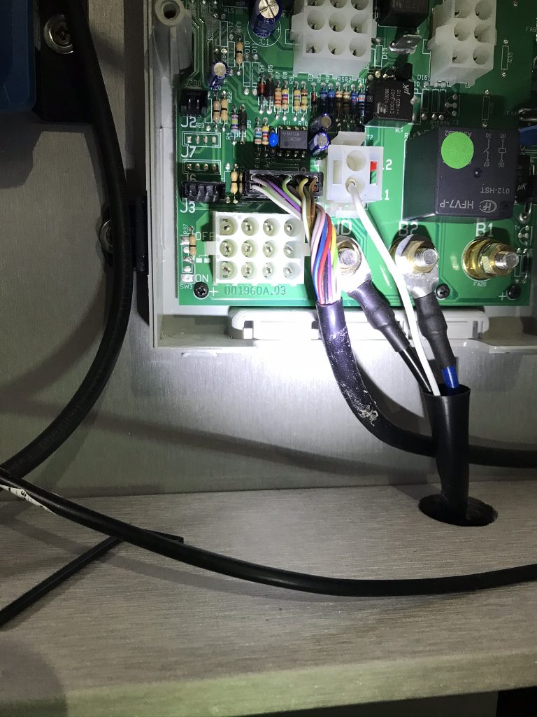
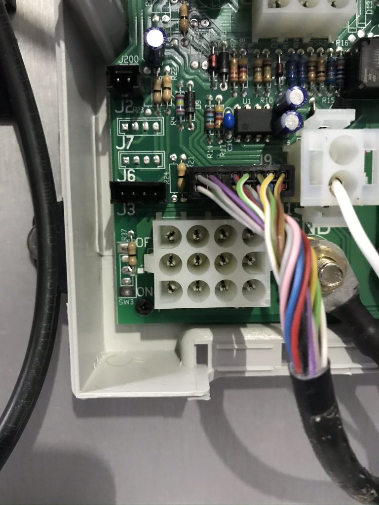
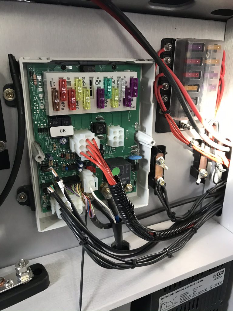
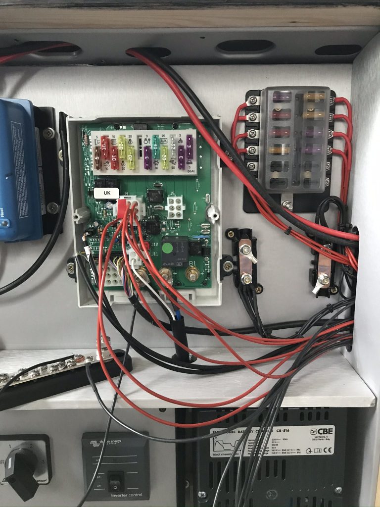
Below: Inside the CBE 12 volt control panel. The red cables are the 12 volt power feeds to various applications like the Internal Roof Lights, Awning Lights, Fridge etc.

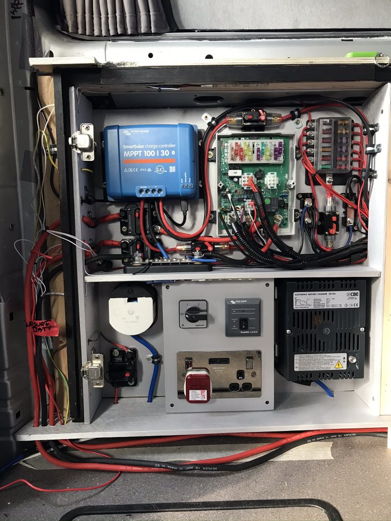
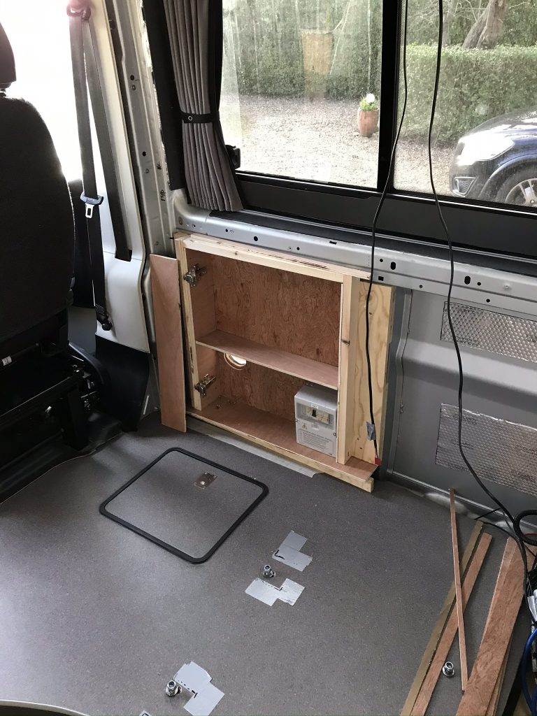
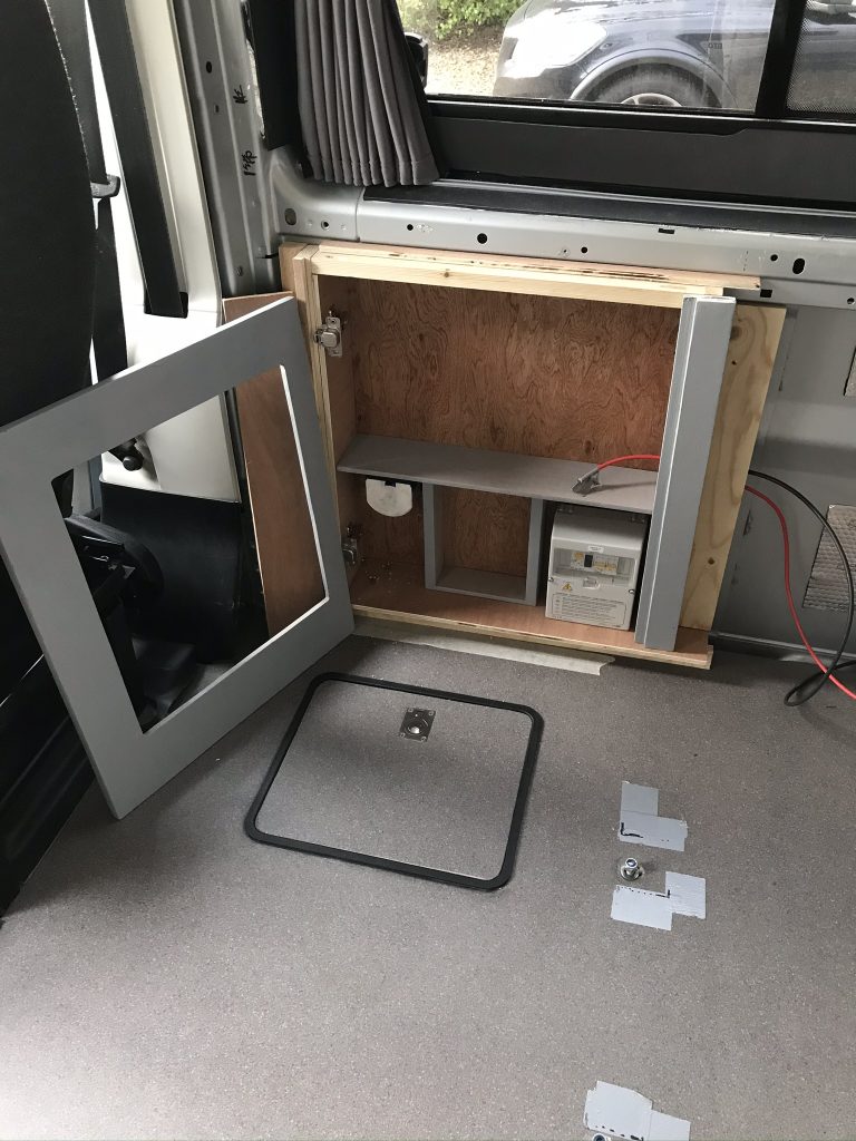
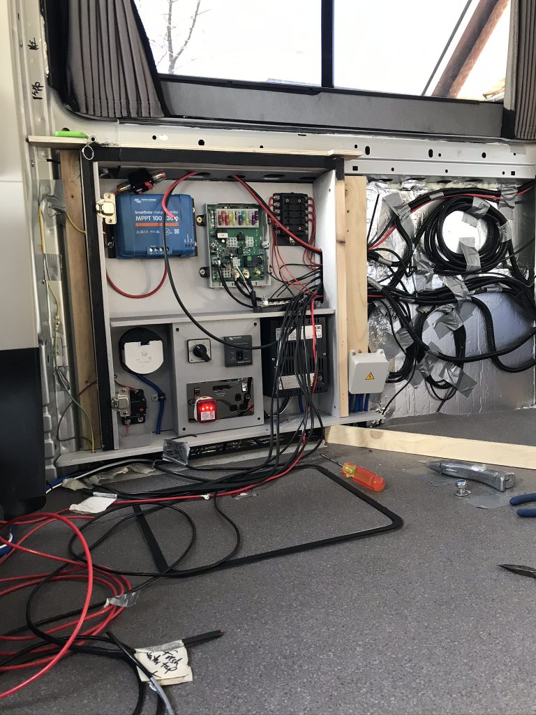
Below: On the right I have added a 12volt fuse box. The CBE is fine but a little limited to how many 12 volts devices you can have. Therefore I have added a second box. Many connections will be wired into the van before the final panels are added and many cables will be spare. Its better to have plenty of spare cables and electrical outlets than it is to try and add them after the van is completed.

Below: I have added a small LED Green light it just makes it look a little more interesting especially at night. I now have 240 volts and 12 volts working simultaneously.

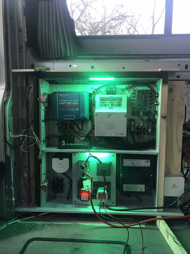
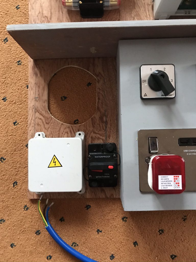
Below Circuit breakers galore: I have added circuit breaker fuses, this type can be reset. I will carry spare fuses but rather than have to remove and replace a regular fuse this method allows the circuit breaker to be reset.

The advantages of circuit breakers: If you look below I have a 40 amp circuit breaker on the feed from the solar panel to the Victron MPPT Box, this allows me to totally disconnect the solar panel energy before it reaches the Victron box, I can also disconnect the power as it leaves the box before it reaches the battery. Also every part of the electrics can be turned on or off.

Prepared For Lithium Batteries: Although I am not adding Lithium at this stage I will add them later (see LifePo4 in the column on the right of this page) the battery to battery charger (not shown) is set -up for lithium (I will show later). Many LifePo4 Batteries now come with a built-in BMS (Battery Management System) which is basically a circuit-board with temperature censor, and charging cut off, many also have Bluetooth Monitoring. Charging a lithium battery in zero temperatures could kill the battery. Even with a BMS and a temperature sensor in place the solar charger will try to put a charge into the battery without you knowing. The battery should sense what is happening and protect itself but by having circuit breaker fuse you can disable the solar charger or any part of the electrical system by the flick of a switch or in this case a press of a button.

Flux Converter Part 3

The van is about to get its first 240 volts Mains Hook Up Power. The consumer unit is being wired using Blue Artic Cable.

Below: The first bank of 240 cables are added, the second bank will be used later

Below: This is the remote switch to control the Victron Inverter. Because the inverter will be housed in a box under the drivers seat then I dont need to go under the seat to turn it on or off. I can simply flick this easy to access switch.

Below: some of the 12 volt cabling has been installed and the CBE 12 volts power control unit has been added. This unit also has a split charge relay (it is able to use the engine to charge the leisure batteries). However, I will show how to by-pass or remove this function from the circuit board later as I plan to use a more sophisticated battery to battery charger.

Below: The two large Black Cables are as follows, a feed from the Vehicle battery and a feed from the Leisure batteries. The extra terminal to the right that doesn’t have a cable yet is for the CBE 240 volt Mains Battery Charger (16 amp output).

Below: The top block with connector (coloured wires) is for the LCD Display panel. The empty white block underneath is for the Commons (negative cables).

Flux Converter Part 2

I need a bit of careful planning here, there are a lot of components and not a lot of room. I had to decide what items would fit and also look nice in a glass cabinet and what items should be hidden under the internal seats.

I tried a few configurations and made changes along the way as you will see later. I have the 12volt system at the top and the Mains Hook Up with 240 power at the bottom. I am using a CBE control system with LCD display which I will show later.

240 volts Mains to 240 volts inverter. I decided on a control switch (see below). Both the 240 Mains and 240 volt inverter will use the same 240 volts wall sockets. Its extremely important that the inverter and 240v Mains can never supply power at the same time to these sockets. If it ever did then there would be a large BANG and a cloud of smoke, ok if you want to send smoke signals or impress your neighbours with a firework display but not ok if its inside your camper-van.

Inverter – Mains Control Switch (silver switch box below): Below is a switch, one section is wired to the Inverter, another section is wired to the 240 volts Mains and a third section sends the current down a wire to a consumer unit. Turn the Switch to Number “1” and you get “only” 240 volts Mains Power when on Hook-Up, turn the switch to number “2” turns off number 1 and turns on number 2 which sends “only” inverter Power to the wall sockets after passing through the consumer unit. Thus its impossible to have both the 240 volts Mains and 240 Inverter sending power to the consumer unit at the same time.

Below: A prototype (test) panel is shown below. This is how the switch separates the 240v mains power for the 240v Mains Hook-Up Power and sends it to the consumer unit

Below: Position #1 is 240 volts Mains Power, position #2 is 240 volts Inverter Power (number 3 is spare). The grey switch below is a remote on off switch for the inverter.

Below: planning the layout (which changed several times)

Below is the Hook-Up area and the white electric box, this was later moved to another location, there isn’t a lot of space so what space there is has to be managed carefully.

Below: I am starting to get an idea of the layout. I have made a box for the 240 volts Main Switch-over to 240 volts inverter power.

Flux Converter Part 1

What is a Flux Converter? in truth I dont know, its a fictitious appliance from the movie Back to the Future. I thought it appropriate I call the electrical system on the van the Flux Converter, this unit powers the internal vehicle which in a “round about way” is used to transport us to a different location. It would be nice if I could set a date into the future but I cant, well not at the moment.

Where to put the electrics and batteries? Lets start with the batteries, the best location would be to have them as close to the vehicle’s starter battery as possible. Often in many camper-vans the electrics and batteries are stored in the rear of the vehicle and this means a long run of wire and in some cases a “voltage drop“, in other words its better to have a shorter cable than it is to have a longer cable even if its thicker (although its not essential).

Location: One place I considered was to have the electrics under the internal seats (just behind the drivers seat) this meant a shorter distance to the Vehicle Battery (starter battery). Although I did decide on this option there wasn’t enough room to house all the electrics as well as two large batteries under the twin seats.

Why hide the Electrics, why not make them easily accessible? I like this idea so long it could be presented neatly it would give really easy access. For example if I wanted to turn off any part of the electrical system then this could be made as easy as opening a small door and flicking a switch. Also they could be made to look a little “pretty” although I am not sure if pretty is the right word.

I decided to house some of the electrics in a cabinet with a glass door

Electrical Display Cabinet: The top section will house the 12 volt electrics and the bottom section will house 240 volts. Never shall the two meet, these sections will have a divider

Mains Hook-Up Hatch (door)

After cutting out the windows for this Peugeot Boxer campervan, I suggested saving some of the metal panels. Now its time to see why they were saved. The less I have to add to the side of a van the better. In my opinion you cant avoid things like windows and a hatch (door) for the Mains Hook-Up. Therefore rather than leave the Mains Hook-Up door black plastic I decided to use the metal I had cut to make the windows and cover the plastic with the same metal that the van is made from, as below.

Under floor Compartment

Having plenty of storage is an asset and the opportunity to add extra should not be wasted in my opinion. The raised floor section gave such an opportunity. I havent decided what to store there yet, some people store fruit and vegetables as its dark and cool, others store shoes and some keep tools and spare parts.

The hatch frame is available from below. I have to add it is a little expensive as its very simple injection molded pvc (made from low cost tooling). However, once fitted its sturdy enough.

O’Leary Motorhomes
314 Hull Road
Plaxton Bridge Road
Woodmansey
East Riding of Yorkshire
HU17 0RT

Telephone : 01482 868632 – 01482 880044
email: info@olearymotorhomes.co.uk

https://www.olearymotorhomes.co.uk/autocruise-inspection-hatch-frame-2-black-77-p.asp

Latch: Search for “Flush Mount Stainless Steel Pull Lift Ring Handle Boat Door

Side Window Curtains

If you look at the images below it may seem strange why curtains have been added before the internal fittings have been completed. This is because I decided to use manufactured interior paneling and in order to fit the curtain tracks I need good access as later the tracks would be partially hidden by the paneling.

Curtain Type? The Curtains are supplied by a company called VanX (google them). They are full stretch “black-out” curtains and also well insulated. Its impossible to see through them and they offer excellent thermal insulation when closed. I was so pleased with them that I later bought another set for the front cab area, however, these will be fitted last.

Price: At the time of writing is £158.97 for two front windows and Barn-door (drivers cab) with rails as a full kit. Or £105.98 if you only want the two front windows (kit)

Forming the shape of the curtain rail: Before you start you need to form the shape of the curtains rail. To do this a small jig is supplied that allows you to bend the rail. Be careful not to have any extreme angles or curves or you will “nip” or close the track and the curtains will not close.

Now its time to repeat the process on the other side (sliding door).

Where to buy:

Van-X-Van Ltd,
Van-X House, Unit 1, Dewsbury Road, Fenton Ind. Est.
Stoke-on-Trent, Staffordshire, ST4 2TE

01782 280 888
01782 454 897

VanX Link

Raised Floor and Vinyl Floor

In order that the Internal seats are at the same height as the two front seats (drivers and passenger) it was necessary to raise a section of the floor. The Van came equipped with a double front passenger seat. This was removed and replaced with a single seat. The double seat was then added inside the van around the table (table to be fitted). The choice is A) make the double seat taller or B) raise the floor the double passenger seat sits on. I chose option B and raised the floor. This idea appeals to me as it also allows the opportunity for some under floor storage.

Floor Covering: There are many types to choose from, wood, carpet lino (vinyl) etc. I decided on lino as its easy to clean and is tough. The lino below is used in homes, offices and public buildings, it has a long life and should last the lifetime of this vehicle. Its also cushioned, this means you could walk on it with high heel shoes as most indentations will spring back out. The area covered isn’t vast so its worth spending a little extra to get good quality. I paid around £150 ($185) and could have easily bought some for £60, however, I think it was worth the extra I paid.

Milescraft Tool (Kreg Tool): This is a great way of joining two pieces of wood together, rather than explain in text I will let the images below show you how this works.

T Trim – Search For: 10 METRE DARK GREY FURNITURE T TRIM knock on edging caravan,camper van,motor home spares

Swivel Seats

Its time to add swivel seating as this can be a great addition to any van as it allows the front two seats to be used as interior seating.

Why Change the Seat Bases? You dont need to change the supports the seats are fitted to, you can use the bases that came with the van. However, if you do your original seats will be 40mm higher. Some people use the seat adjusters to lower the seats as far as they will go but if you try this on a Peugeot boxer (Fiat Ducato and Citroen Relay) you may find they dont go low enough. I tried it and I didnt like it, therefore I ordered specially made seat bases or supports that are made 40mm lower than the factory versions. This means that when you fit the swivel unit (which is about 40mm high) the seats remain at the same height as when the van came out of the factory.

Below: You can see the Swivel Plates and also the new 40mm Lowered Seat supports

Warning: make sure the ignition is switched off before unplugging the seat electrics (plug), otherwise you may trigger the “seat belt tensioner”.

Offset Swivel Seats: When you swivel the seats to the 180 degrees specified the seats become more central to the vehicle which gives you effectively more clearance to furniture fitted to the side of the interior. A nice feature as it moves the seat closer to the dining table. These are Sportscraft TUV approved swivels (made in Germany)

Lowered Seat Bases & Swivel Seats:

Jennings CVS Ltd
Unit 19-20,
A Tech-Court Lancaster Fields
Crewe Gates Farm Ind Estate
Cheshire
CW1 6FF
01270 257 417

https://www.swivel-seats.com/product/manufacturer/sportscraft/ducato-x250-single-seat-base-frame/

https://www.swivel-seats.com/product/manufacturer/sportscraft/sportscraft-ducato-boxer-relay-offset-turning-2007-onwards-driver-side/

Interior Roof

There are numerous lining you can chose. Try and get something that can be wiped down and doesnt absorb water because even with the best insulation you can still get condensation and you dont want it to linger in the roof lining.

Which did I choose? Most van builds seem to use a wood based lining thats coated, its common so see this type in caravans. I wanted something a little different so I made the wooden sections and covered them with a man-made Leather Fabric. It has the feel and texture of real leather and can be wiped down so its fairly resistant to water. That doesn’t mean it looks plastic in fact it looks the opposite, if you didn’t know you would think it was high grade leather. This material is available on the internet from many fabric suppliers. I used a public and trade fabric supplier in Manchester UK, they have a warehouse selection much larger than a high street shop.

Below: If you look carefully you may see some wooden strips that have been screwed to the roof with self-tapping screws, they are covered with aluminum tape so its easy not to notice them. These wooden pieces are the base in which the wood rood panels are screwed to.

Below: I used a “template cutter router bit” its a cutter with a small bearing that runs around the edge of the wood you are cutting. It makes cutting a hole for the vent so much easier and also quite fast. It leaves a neat edge.

Below: With a route this hole took around 1 min to cut

Below: Some of the panels end sections didnt sit directly over a beam so they couldn’t be screwed down at one of the edges. I couldnt leave them as the two panel edges would “flop” and move. To overcome this I made a few 60mm X 150mm strips of wood (9mm thick) and attached them to the end of one wood panel. When I fitted the next panel I added some sikaflex to the wood strips so that they would joint together and hold as one. In other words these wood strips allowed the panels to join or lock together a bit like a set of teeth at the end of one panel.

Below: The fabric is being added, first the wood is sprayed with contact adhesive then the fabric is sprayed. Make sure you have wood and fabric aligned correctly because if not your fabric will run off course, take your time here.

Below: I had already added cables to the ceiling and decided to drill a few holes and fit the lights. Power hasn’t been installed at this stage the lights are working off a Mains Power supply which delivers 12 volts. I decided to use “touch-lighting” a on-off switch isn’t required, you simple touch the light you want switching on with your finger. To turn off tap it with your finger. This gives easy lighting control.

I Want Fabric,
Unit 5 Bute Street,
Salford,
Manchester,
M50 1DU,
Telephone: 0161 9250333

The Type of Faux leather used in my camper-van is “Nova Faux Leather Upholstery Fabric, Cream” see link below.

https://www.iwantfabric.com/nova-faux-leather-upholstery-fabric.html

Vehicle Fabrics from the same company

https://www.iwantfabric.com/vehicle-upholstery/automotive-leather

I used 2 Spray-Cans of Contact Adhesive

https://www.iwantfabric.com/heavy-duty-contact-spray-glue-full-case-x-12-tins.html