Bathroom (wet room)

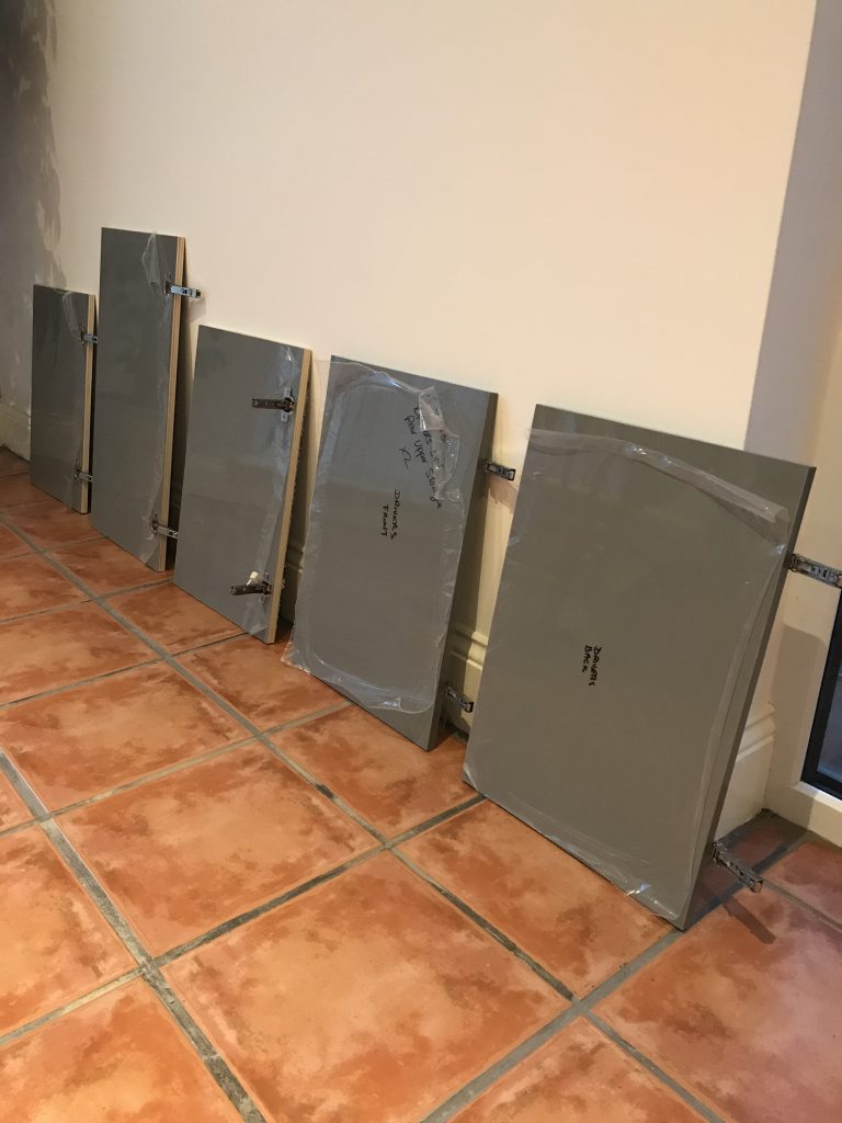
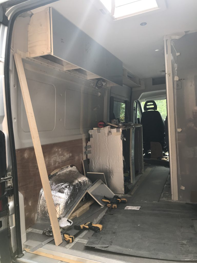
If you have followed the categories in order you will note that I have made the walls for the shower or wet-room but I haven’t fitted them yet. This is because I now need to add white plastic panels to the back of these wall panels. The whole room will be in white and fully sealed (except for around the door).

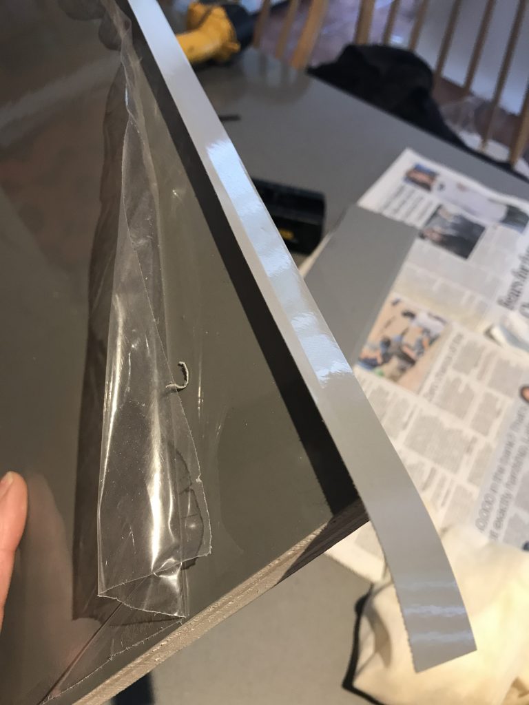
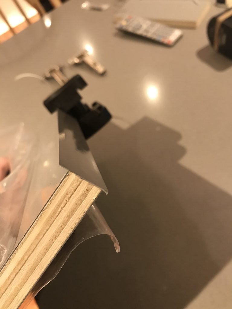
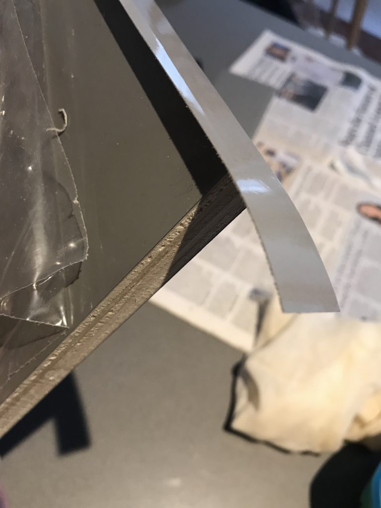
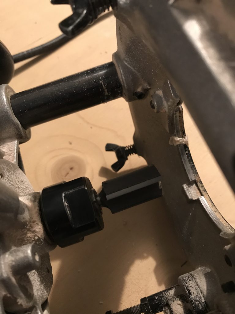
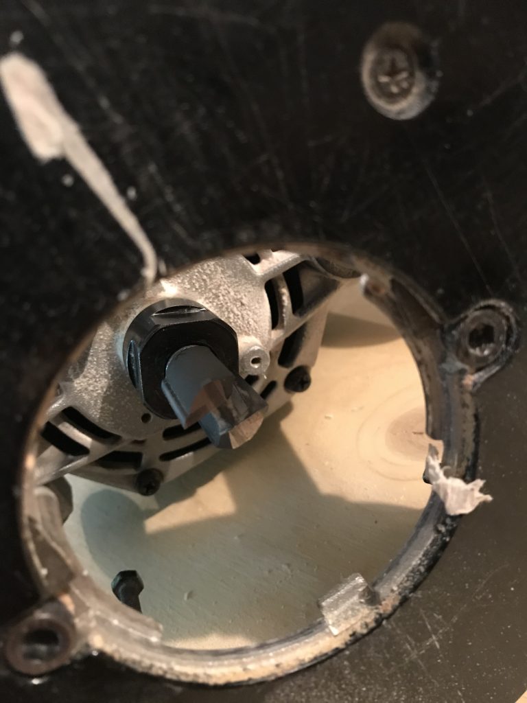
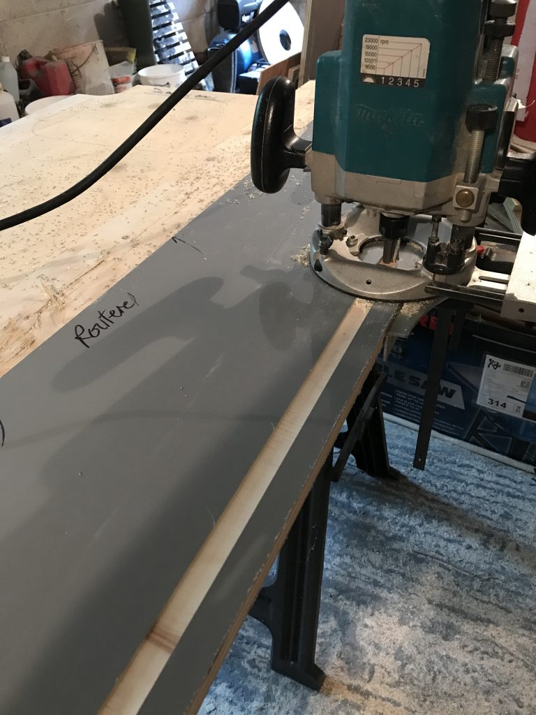
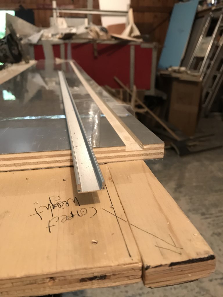
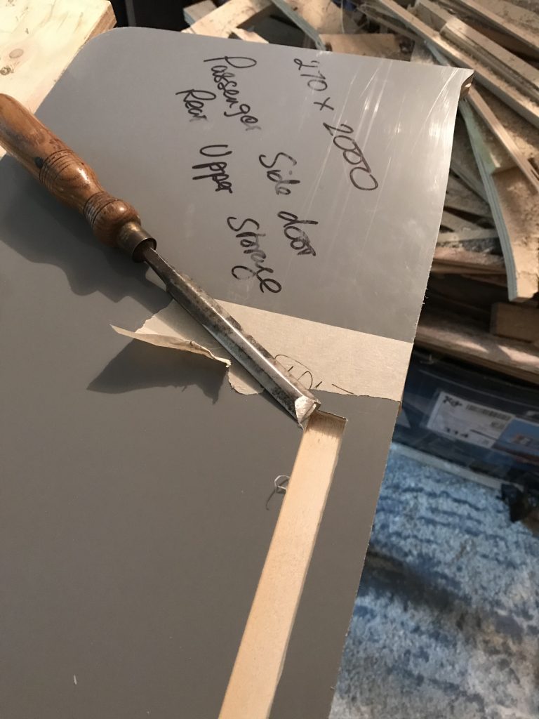
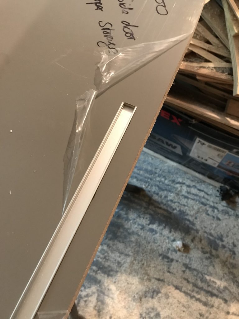
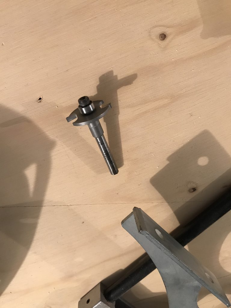
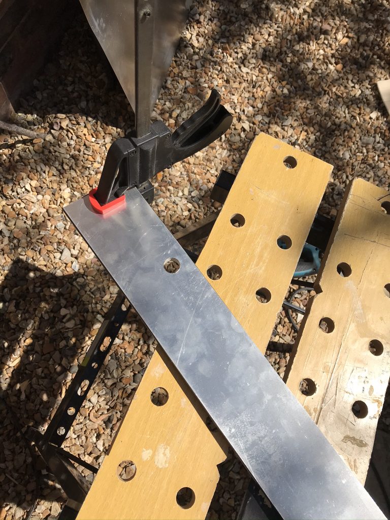
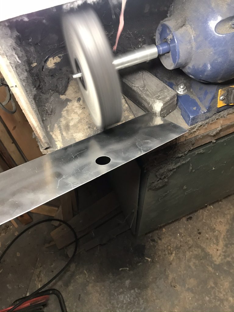
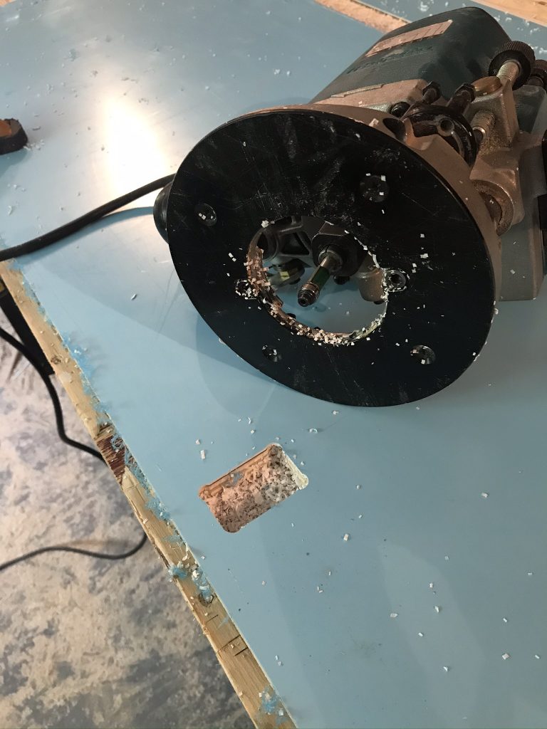
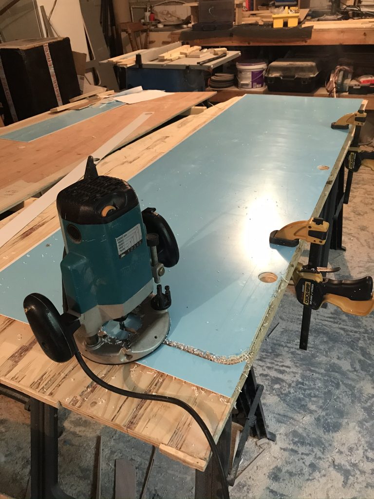
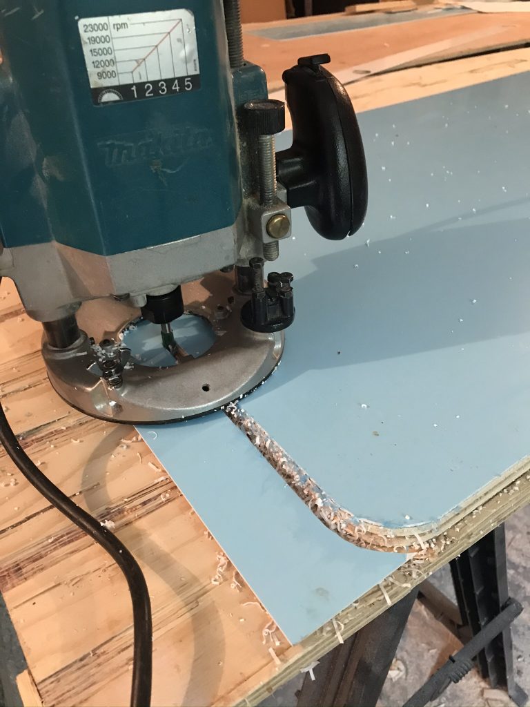
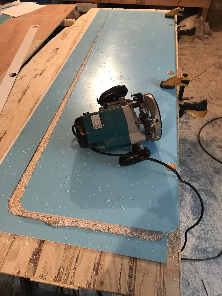
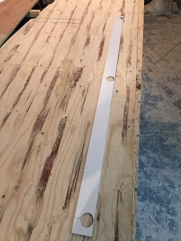
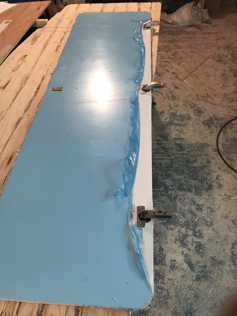
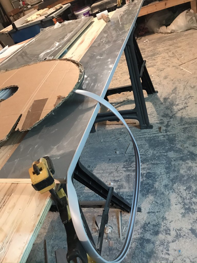
Below: I purchased 1.5mm thick white sheets (8 X 4) this has already been stuck to the bathroom door shown below using Sikaflex 512 adhesive. Its been left with weights on the top overnight to fully set. Its now ready for cutting. To make sure I get perfect edges I am using a ball bearing router (shown below) to cut around the sides. This type of router prevents me cutting into the panel door that’s below the white plastic. Its actually easy to use, just run the router around the edge and the excess is cut away, as simple as that.

If you are wondering why I didn’t add the white plastic wall panel after the wet-room was built? This is because the opening for the door is too small to accept such a large panel. It had to be built before assembly. Be careful you dont make this mistake (not that I did).

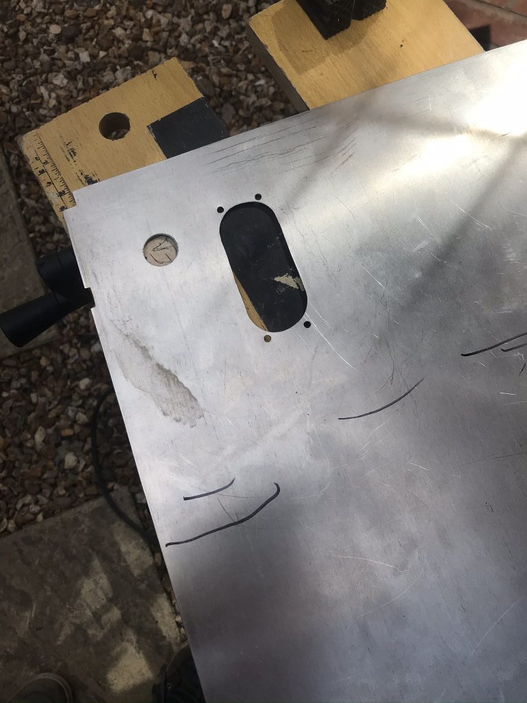
Below: Making the bathroom door

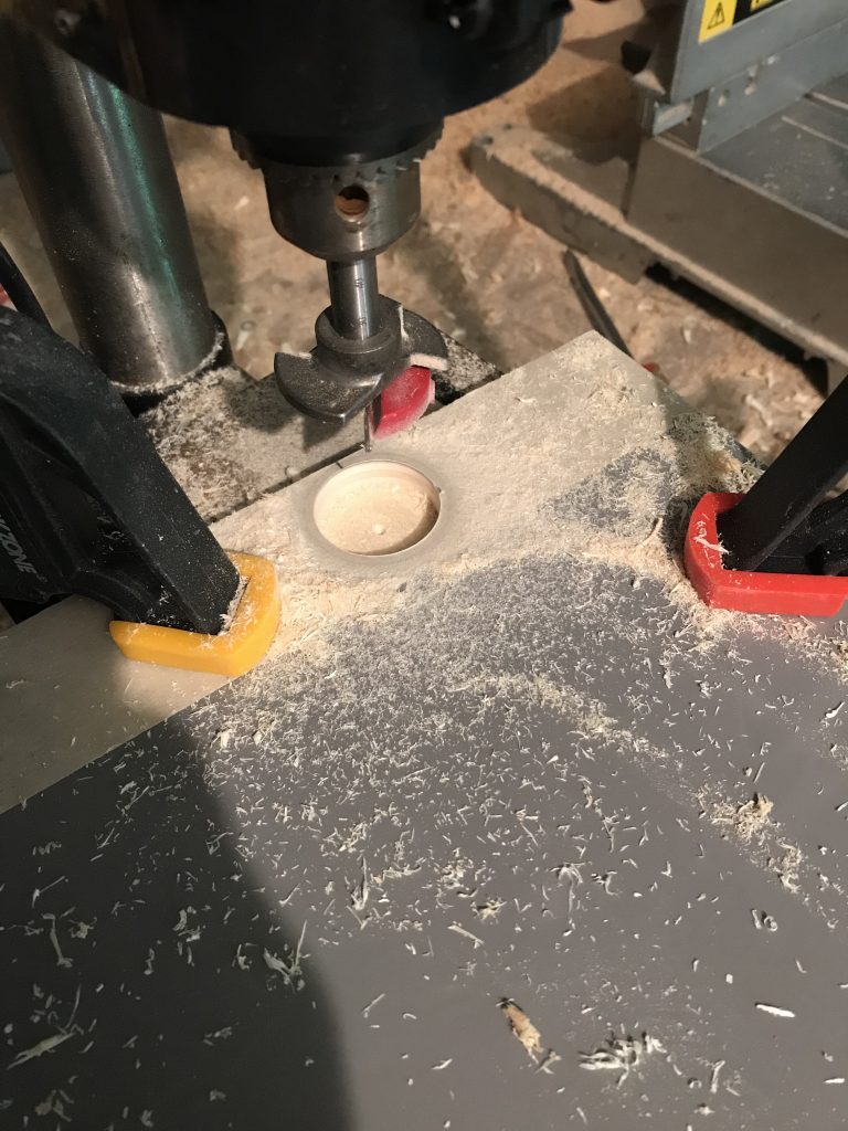
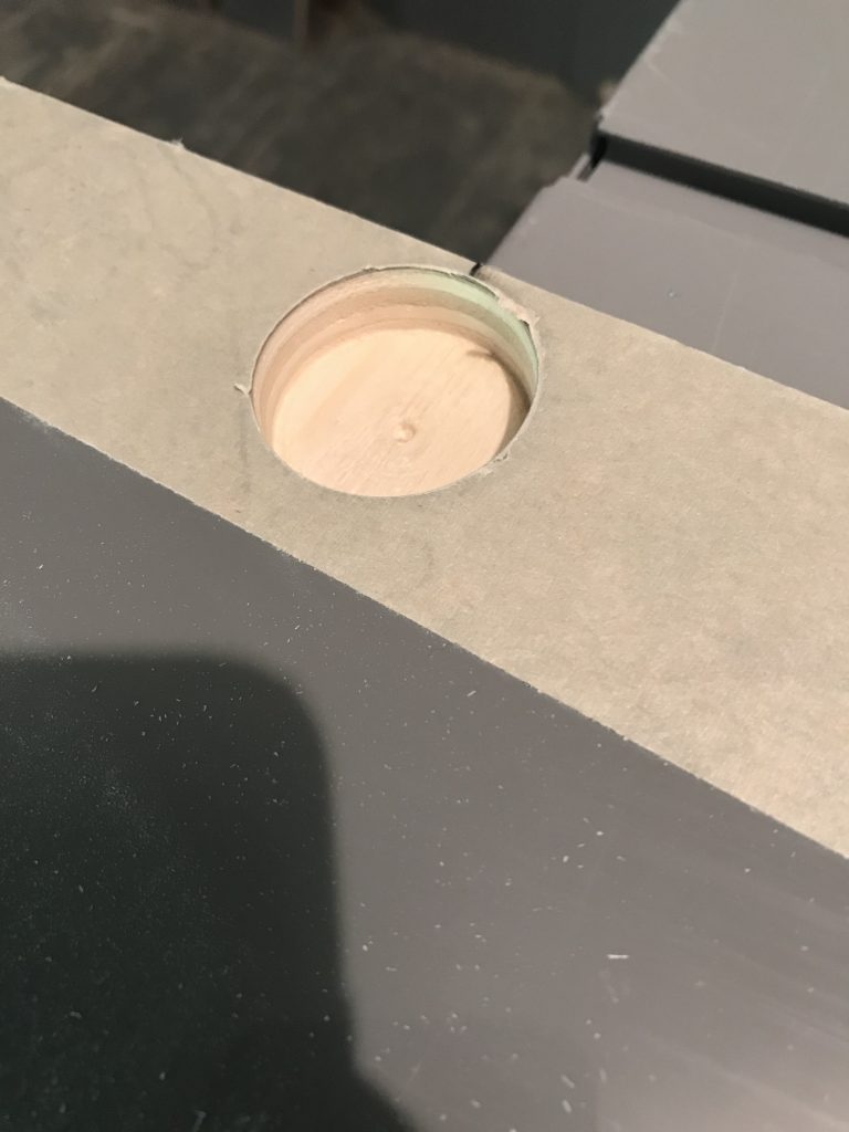
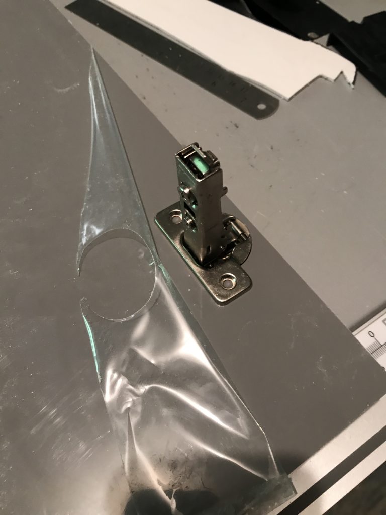
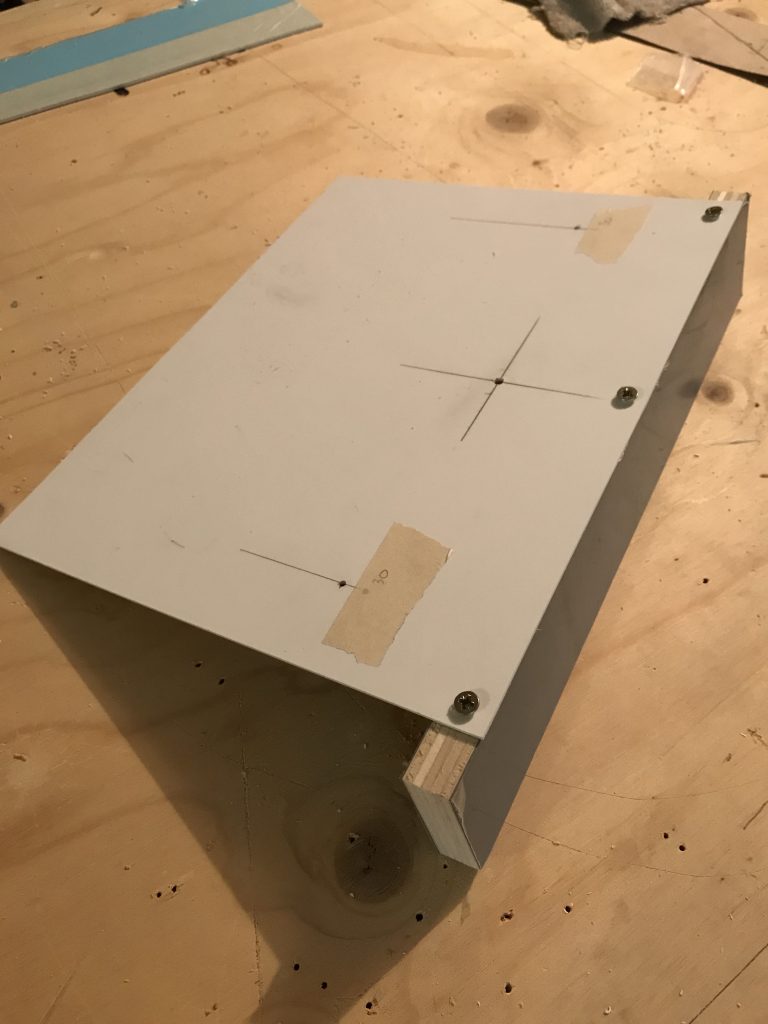
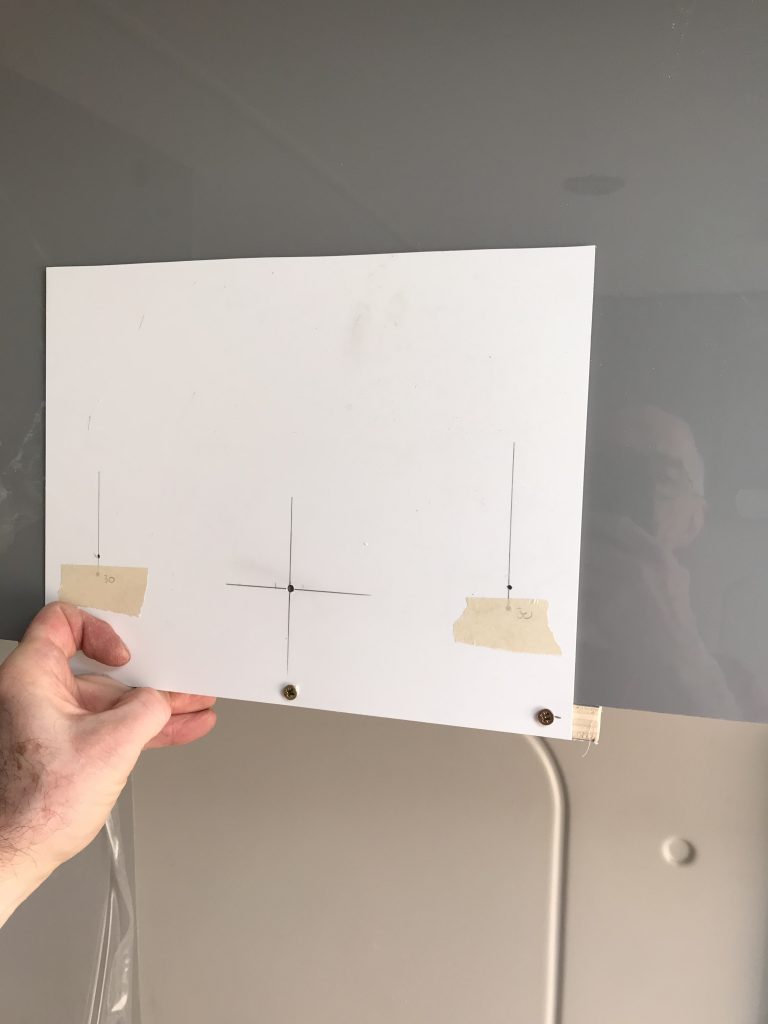
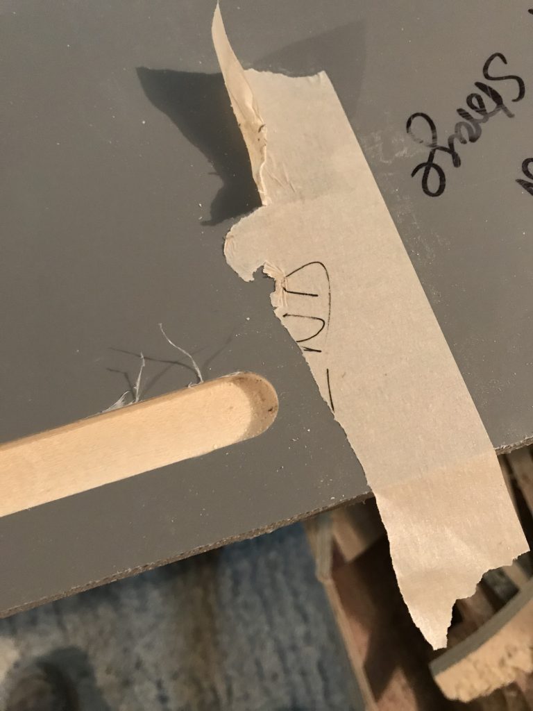
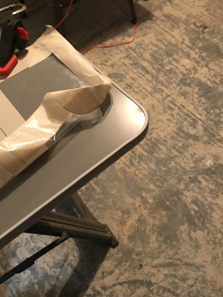
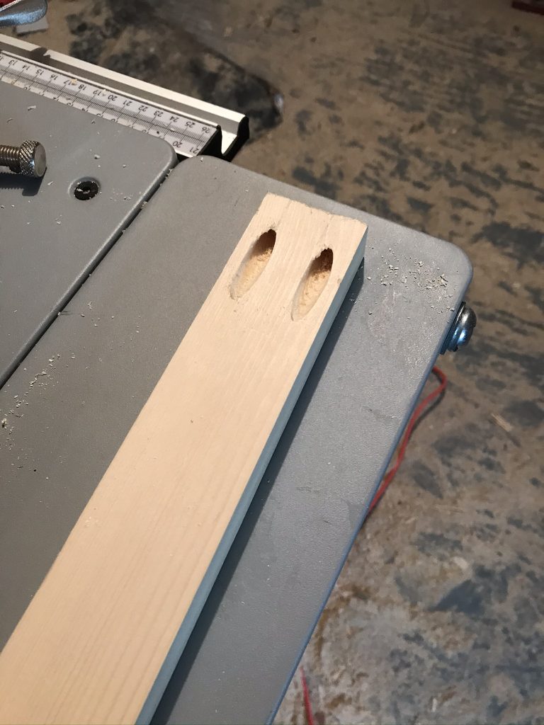
Below: before cutting the holes for the bathroom door hinges I made a simple template so I could check them and also make sure they aligned correctly. It isn’t necessary but it did make cutting safer and easier. I didn’t want to make a mistake at this stage as to make a new door would cost me a lot of time.

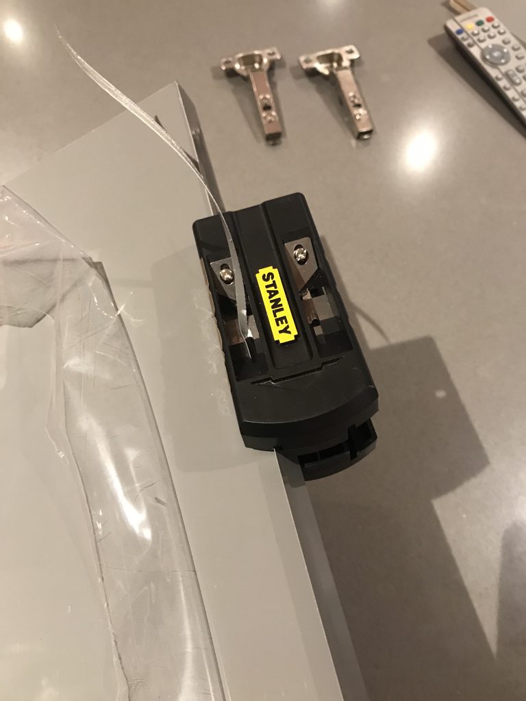
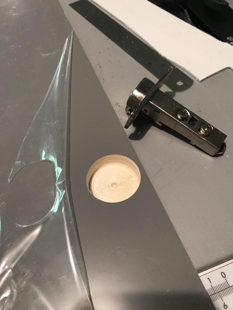
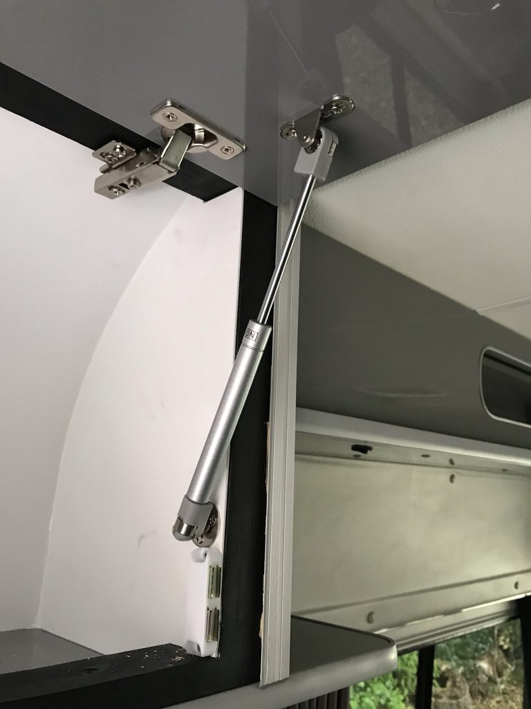
Hinges (shown below) are from

the following company

EVO MOTION DESIGN LTD
6 Westminster Road
Wareham
Dorset
BH20 4SP
TEL: 01929 55 00 00

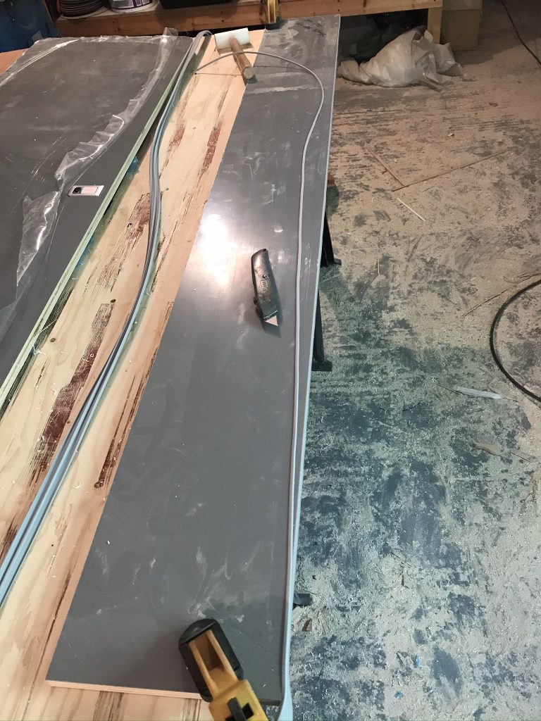
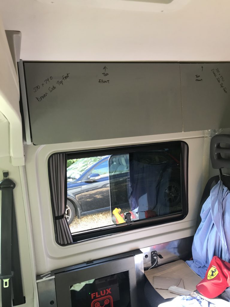
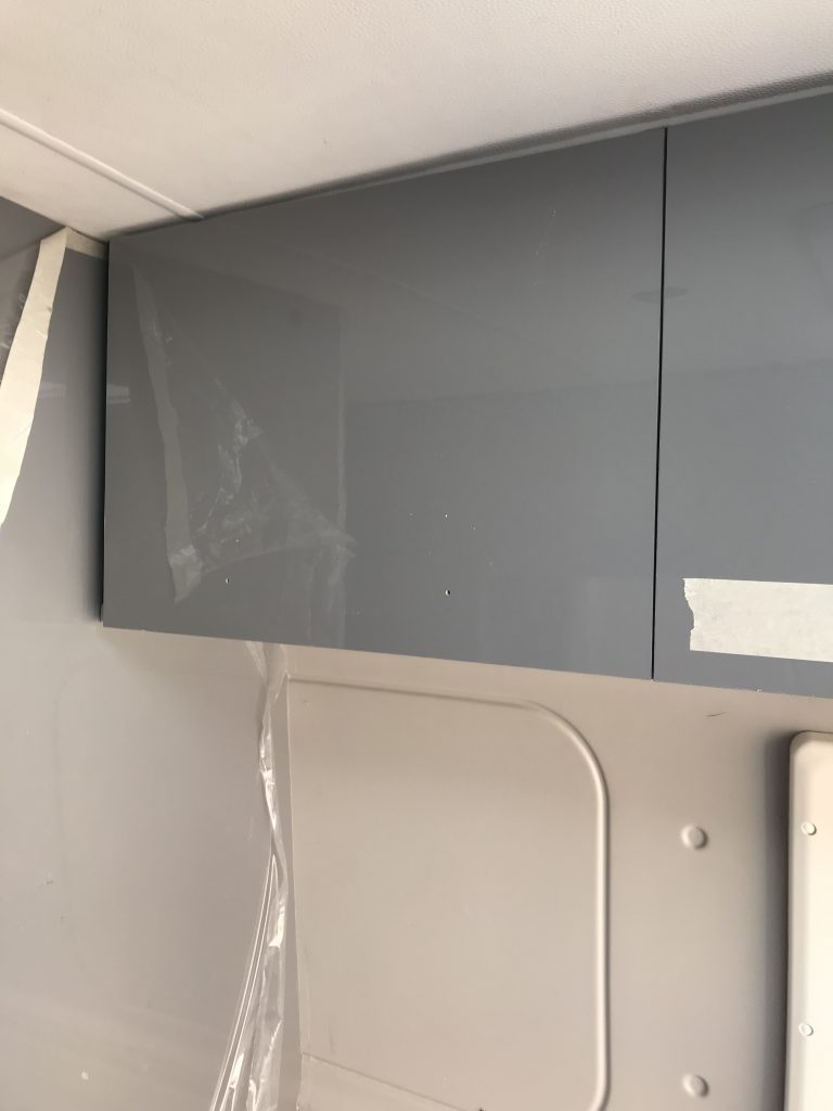
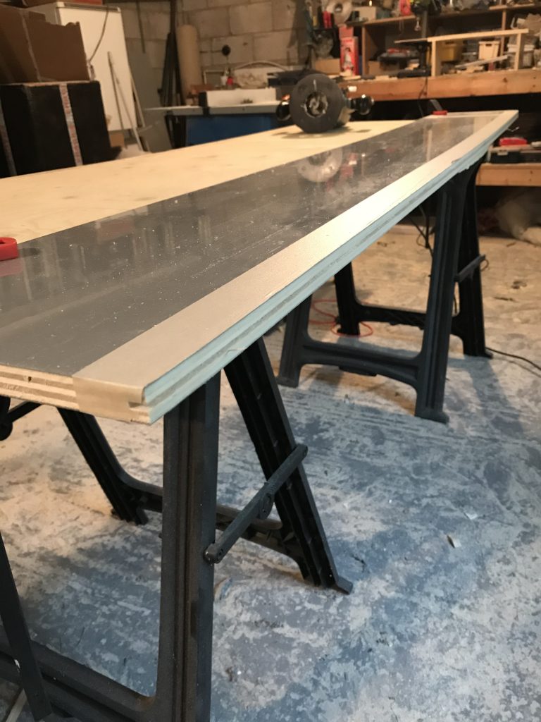
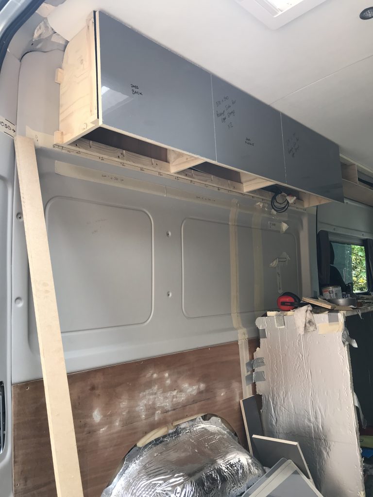
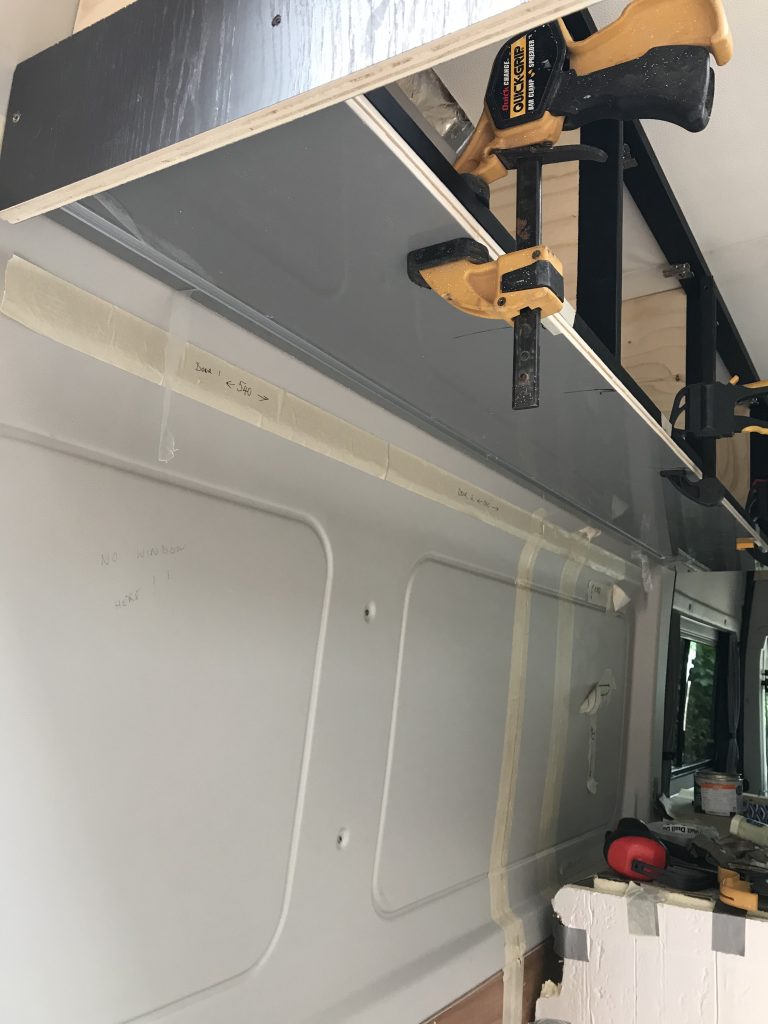
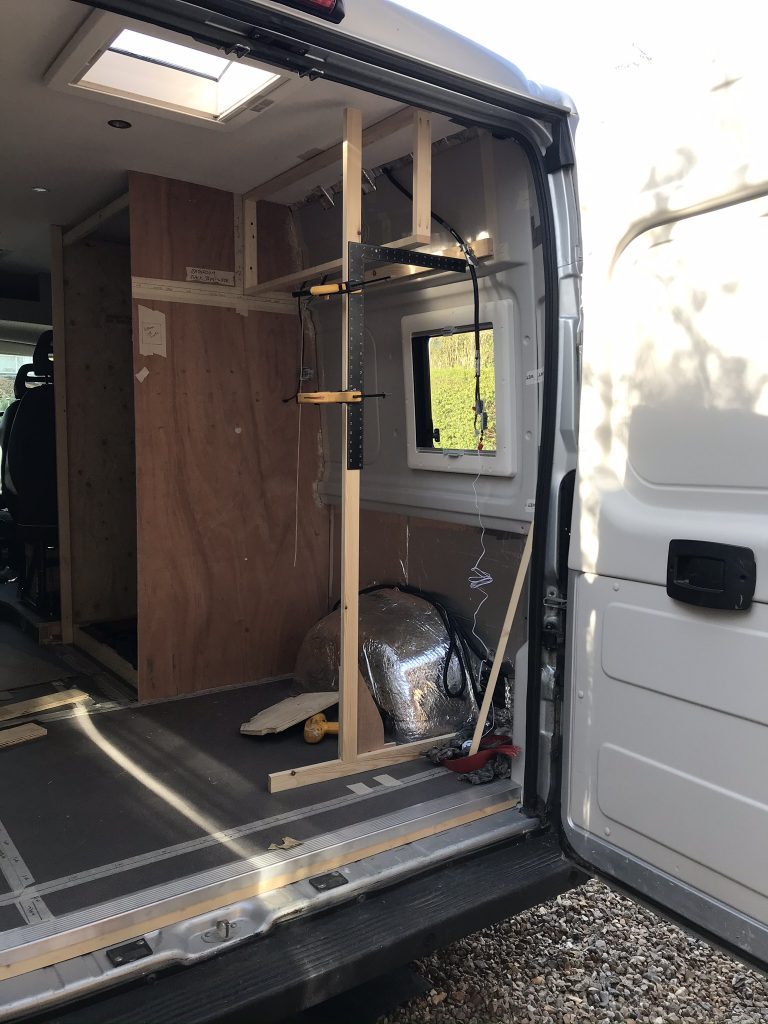
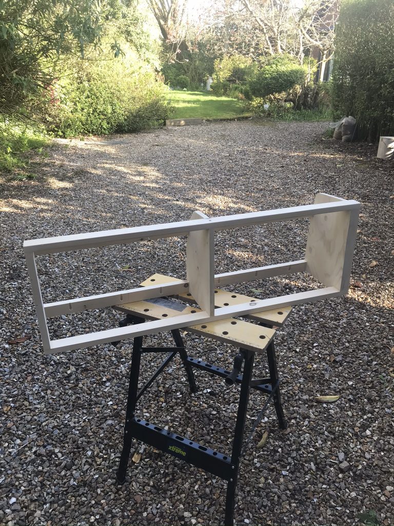
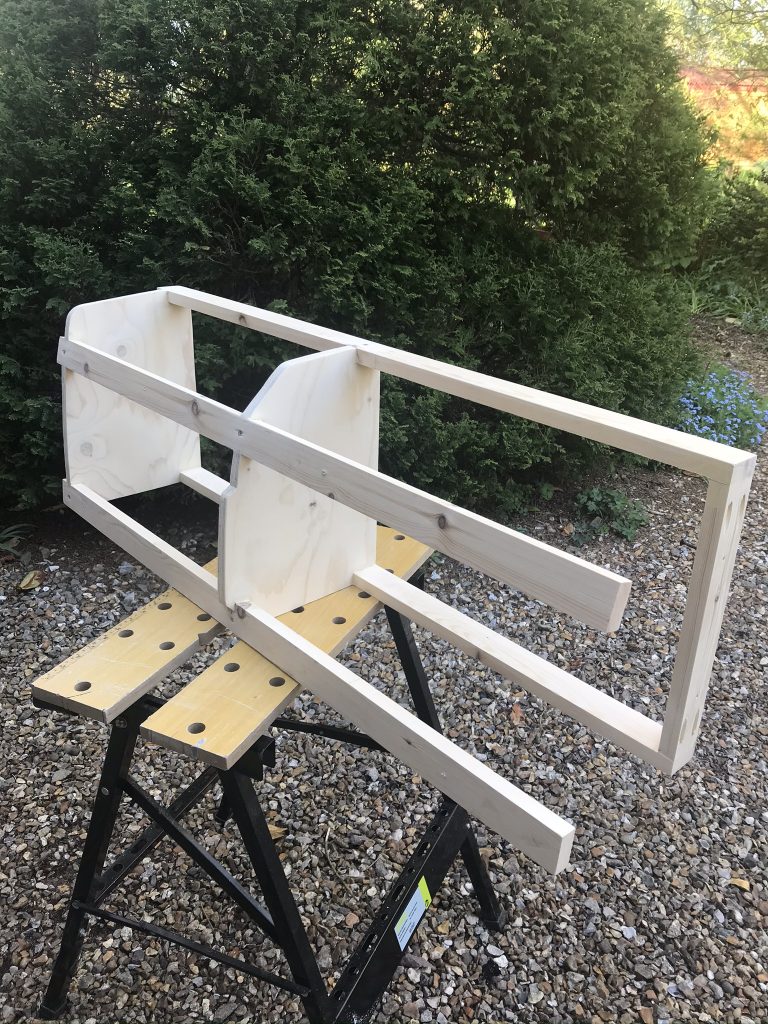
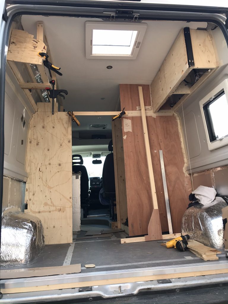
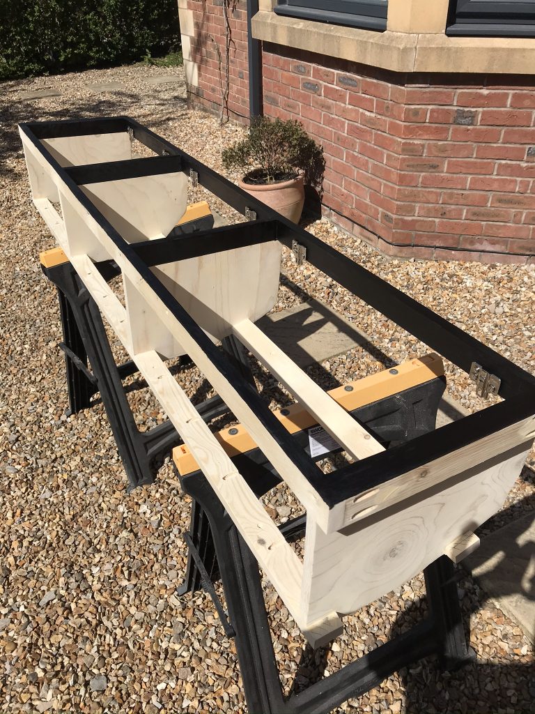
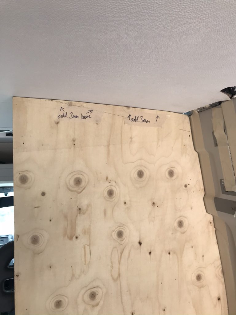
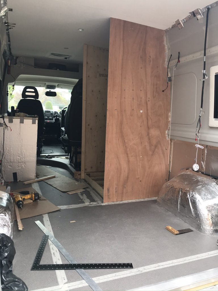
Below: Constructing the front large panel before assembly. Note the White plastic backing panel is already fitted. As mentioned above I needed to fit this sheet before the wet-room was assembled as it wouldn’t fit through the wet-room door.

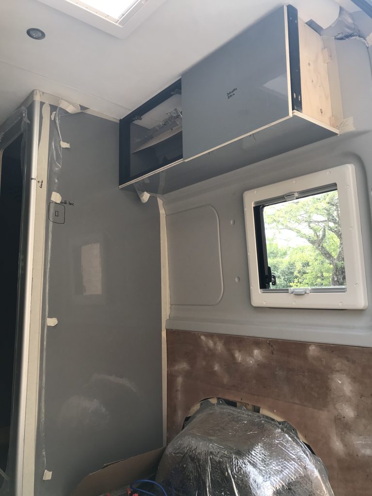
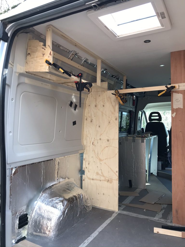
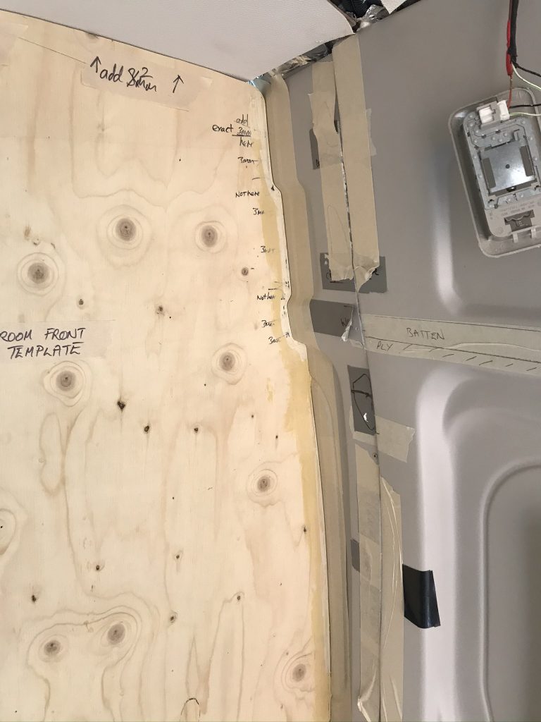
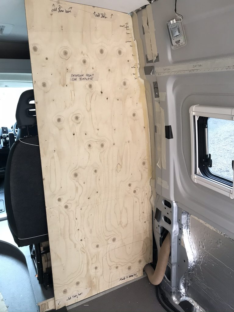
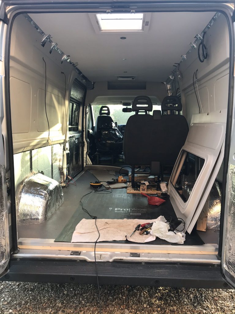
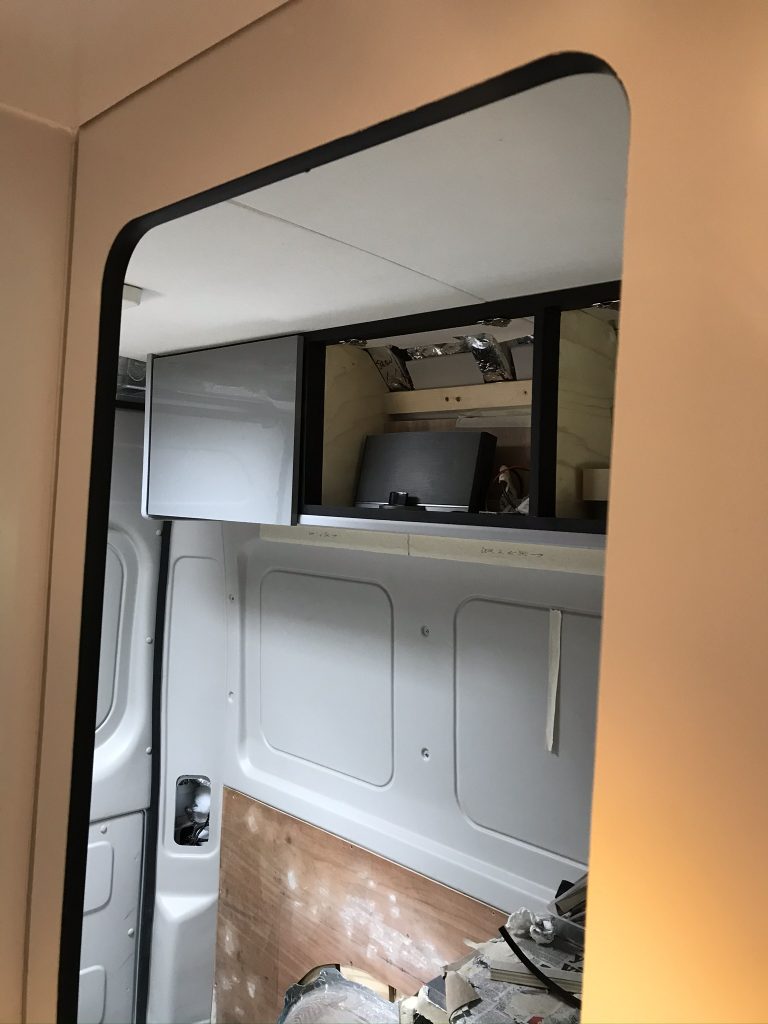
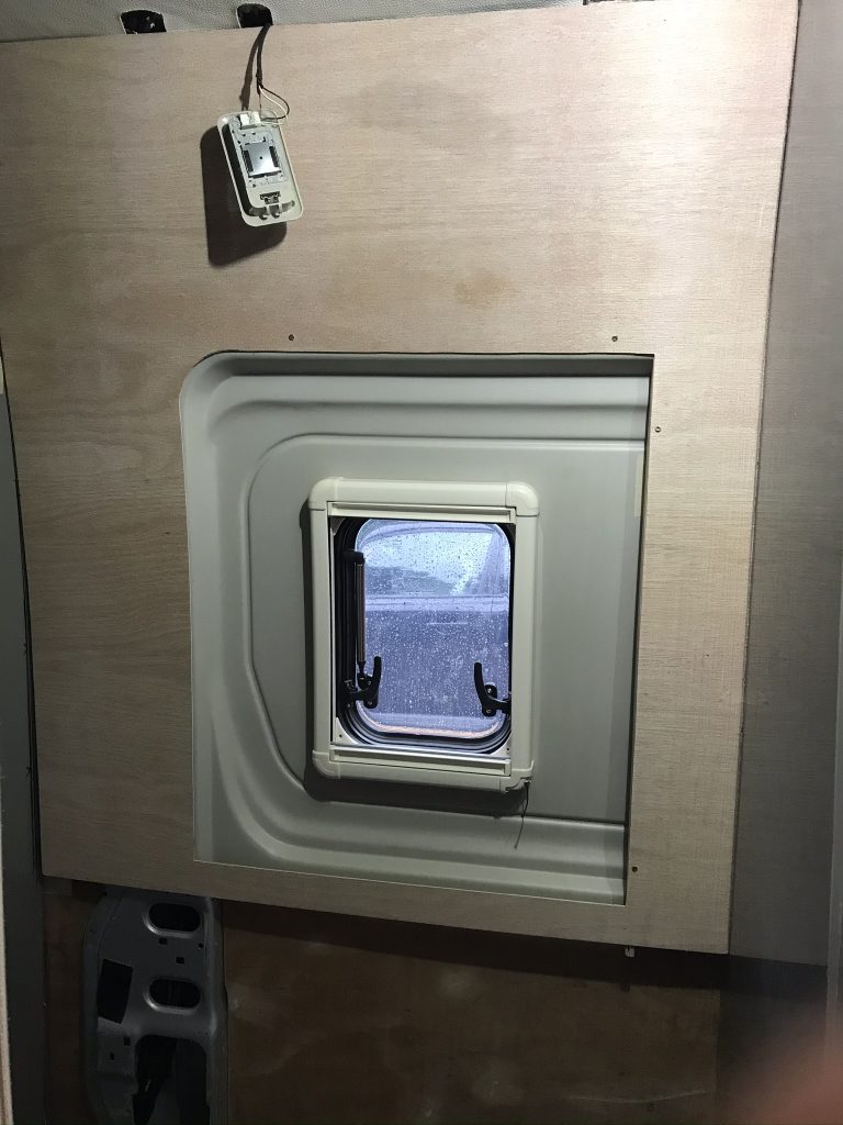
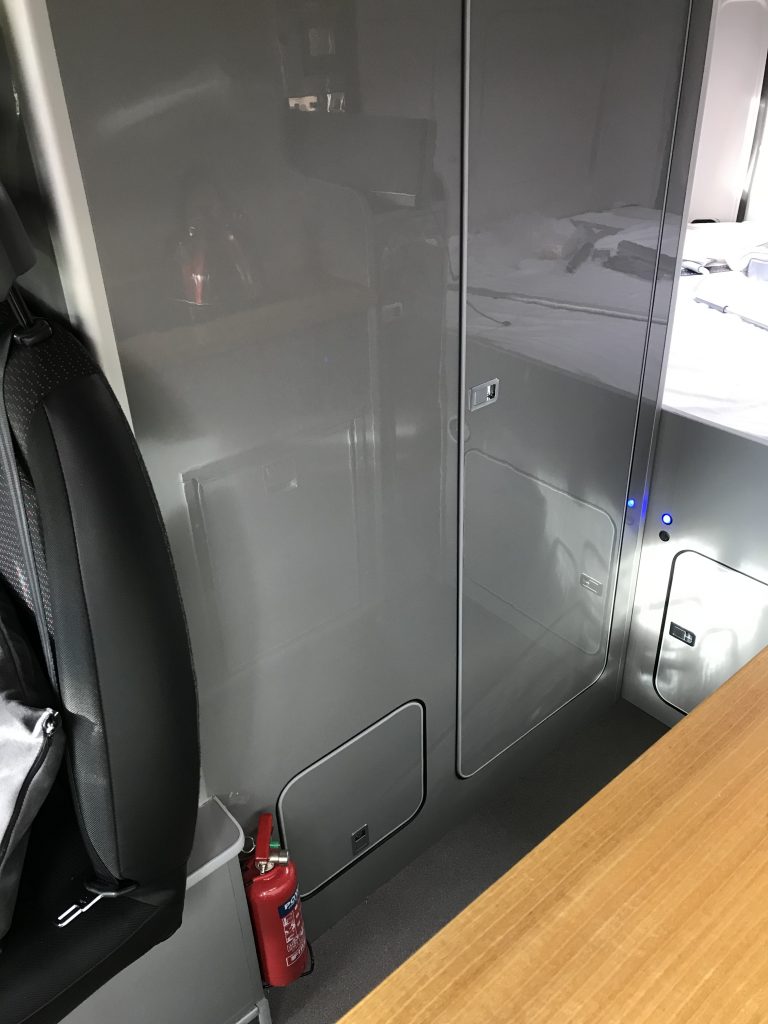
Below: The front panel is now fitted, this is a view from inside the wet-room looking out into the van.

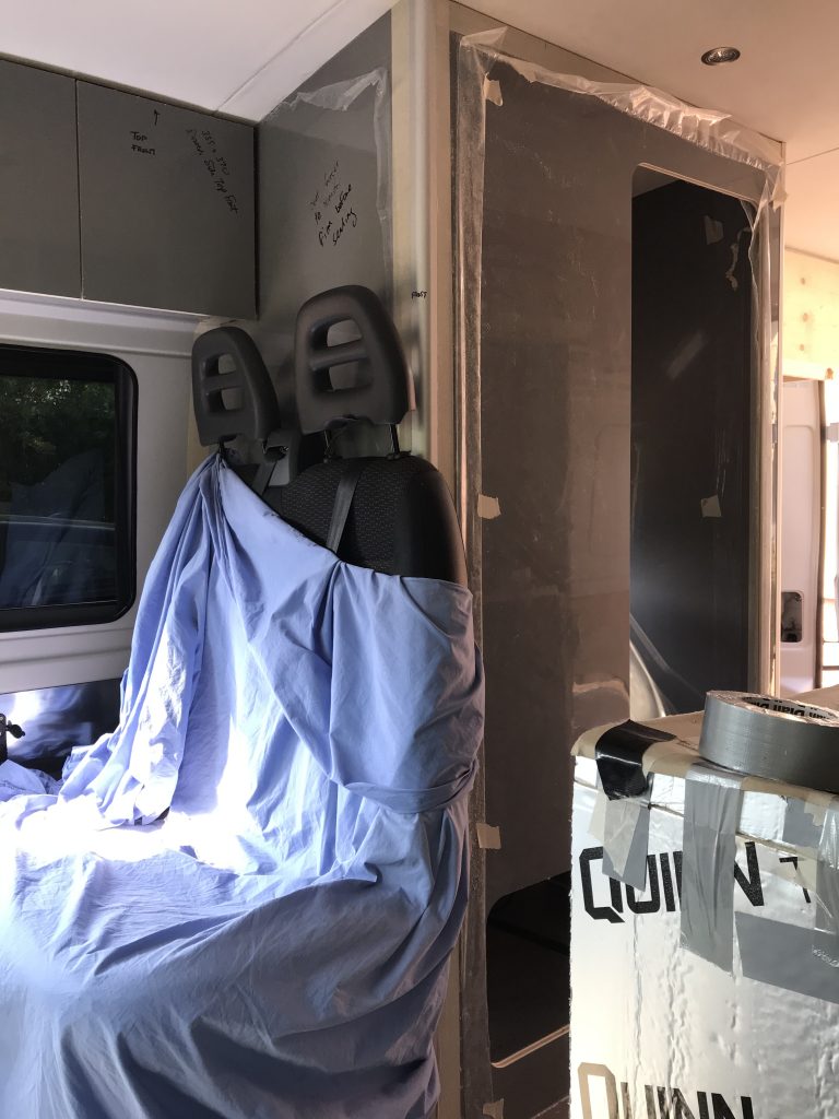
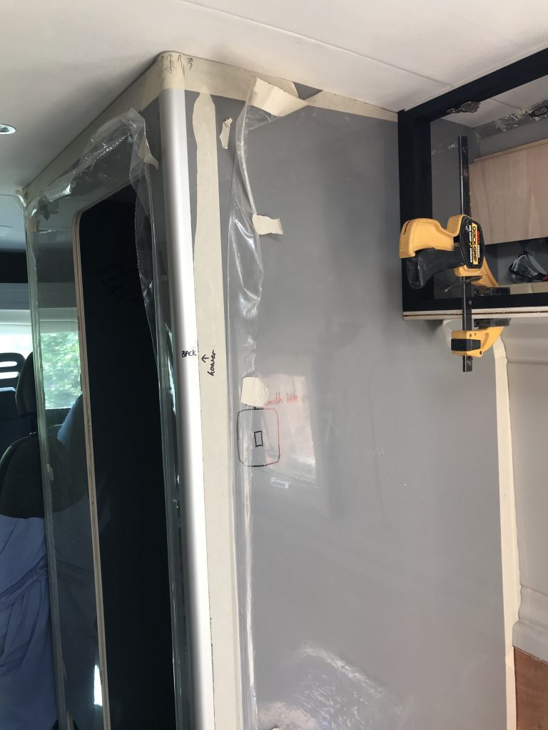
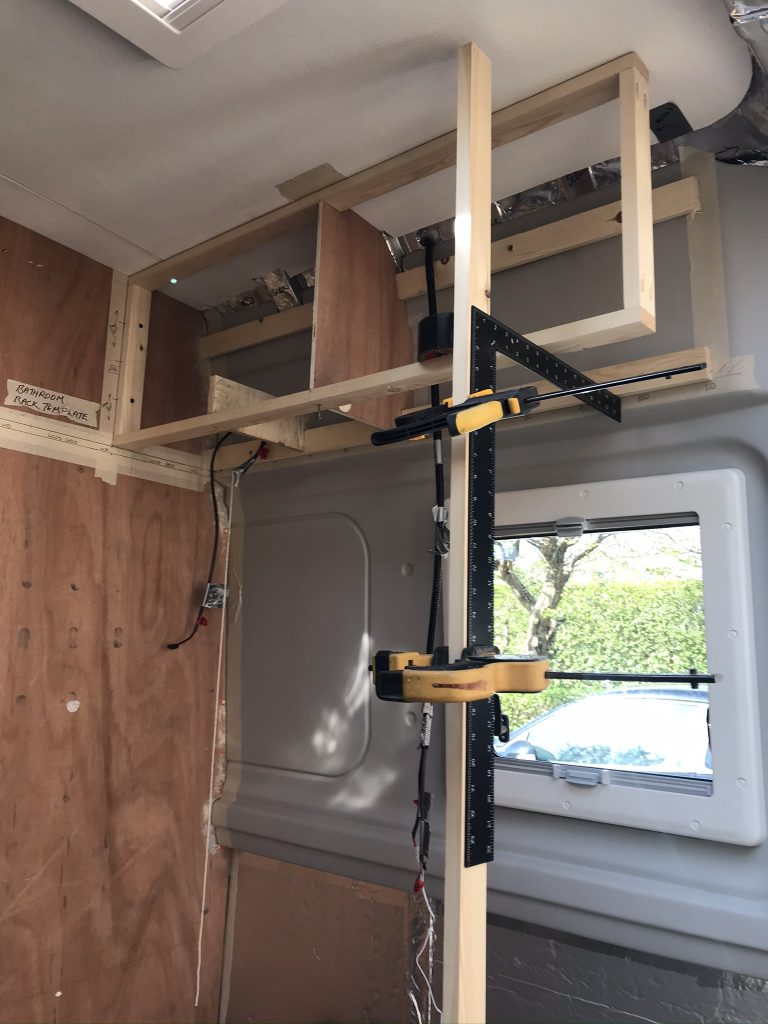
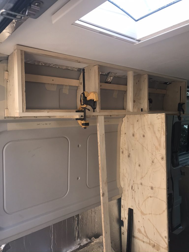
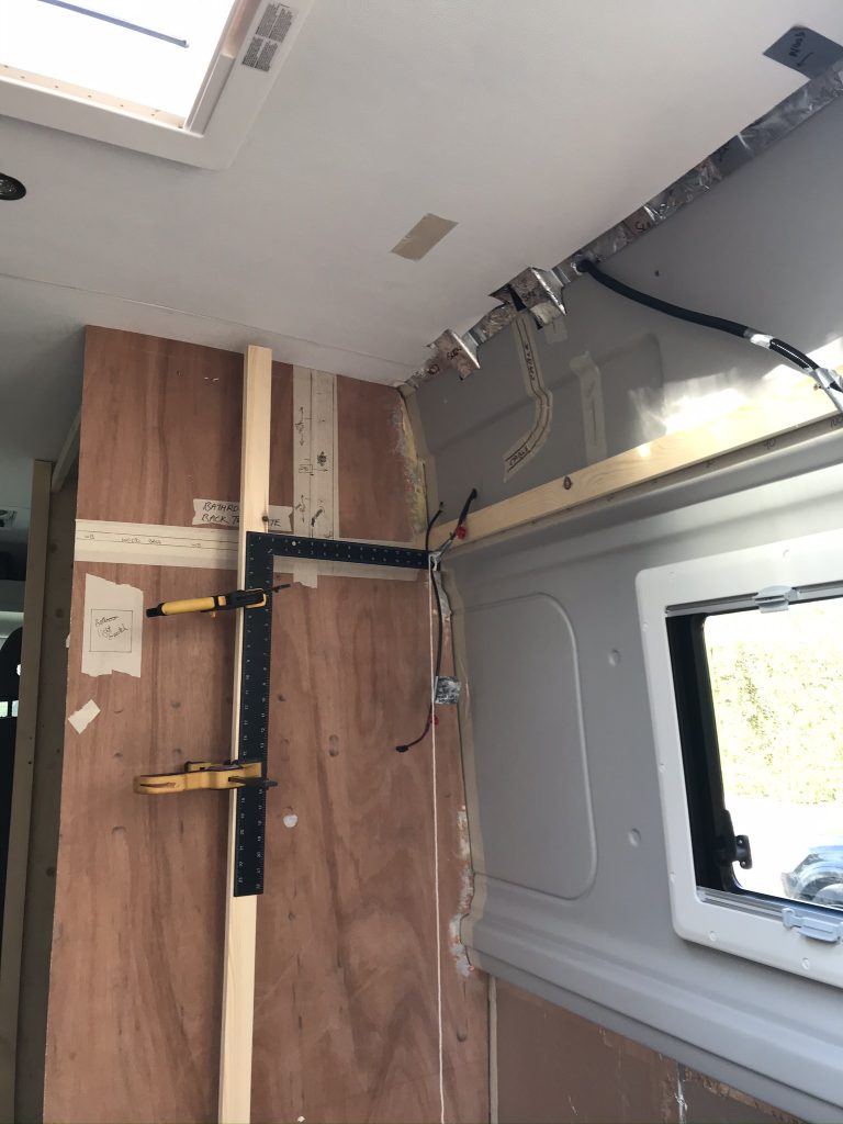
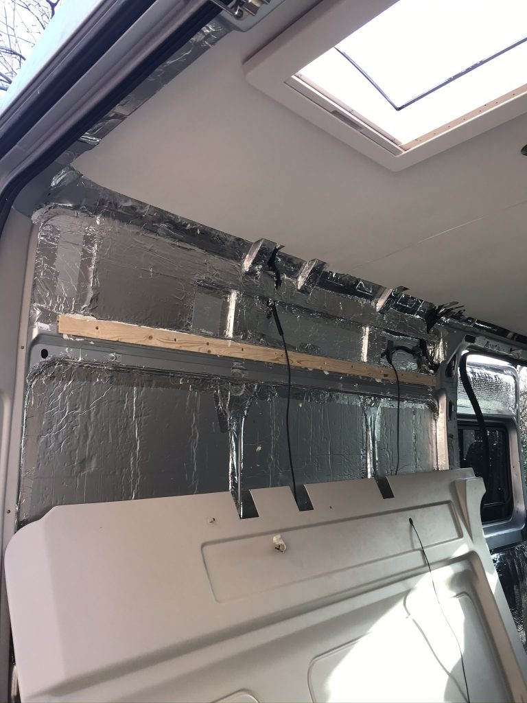
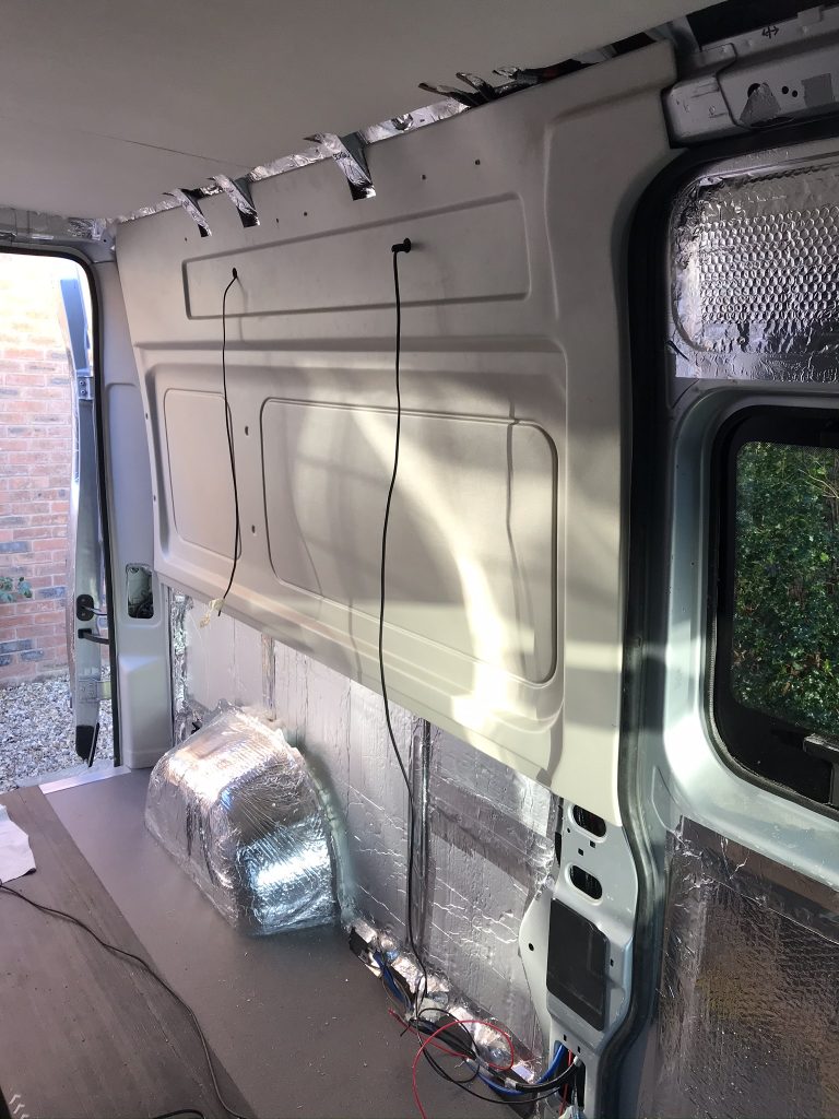
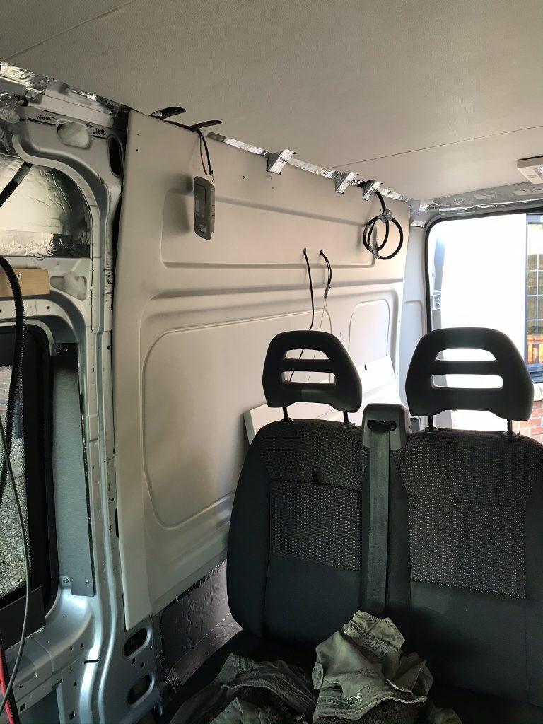
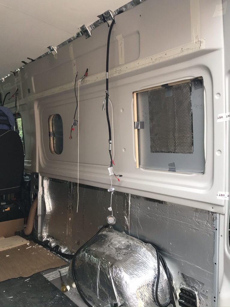
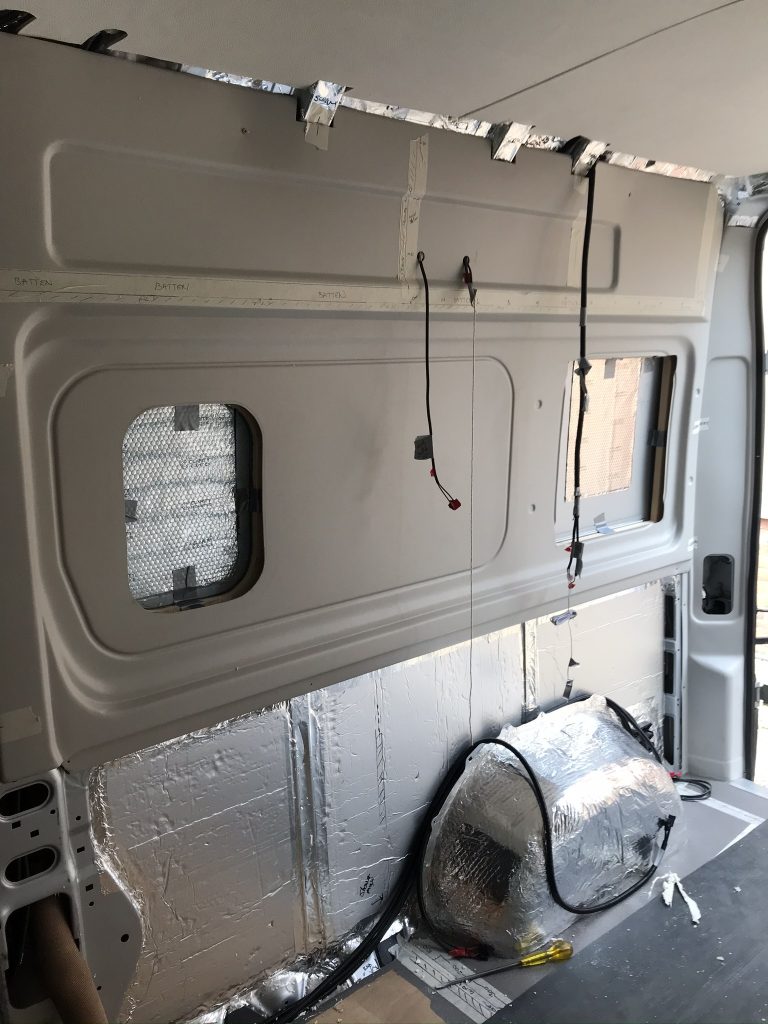
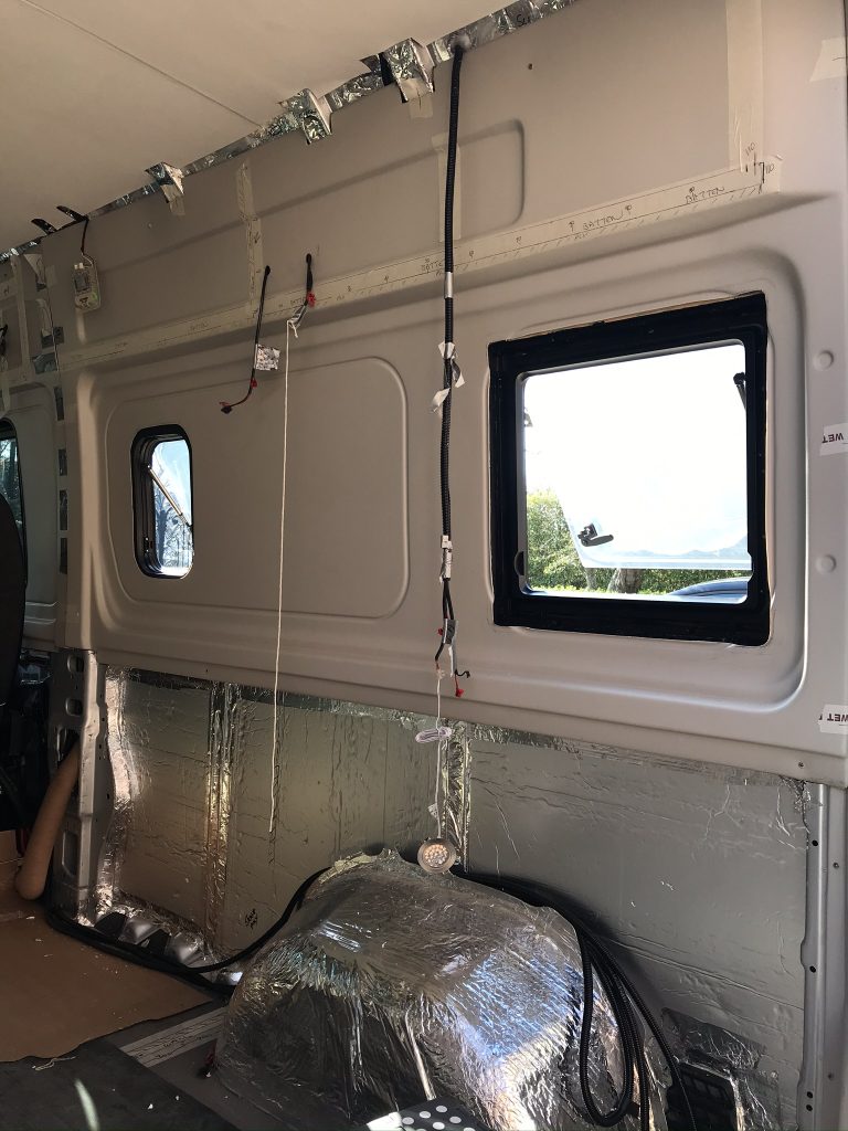
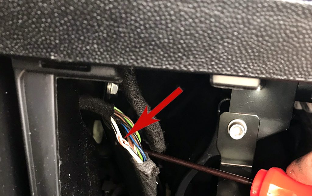
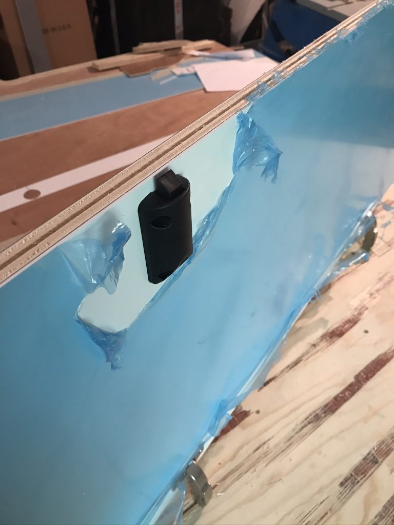
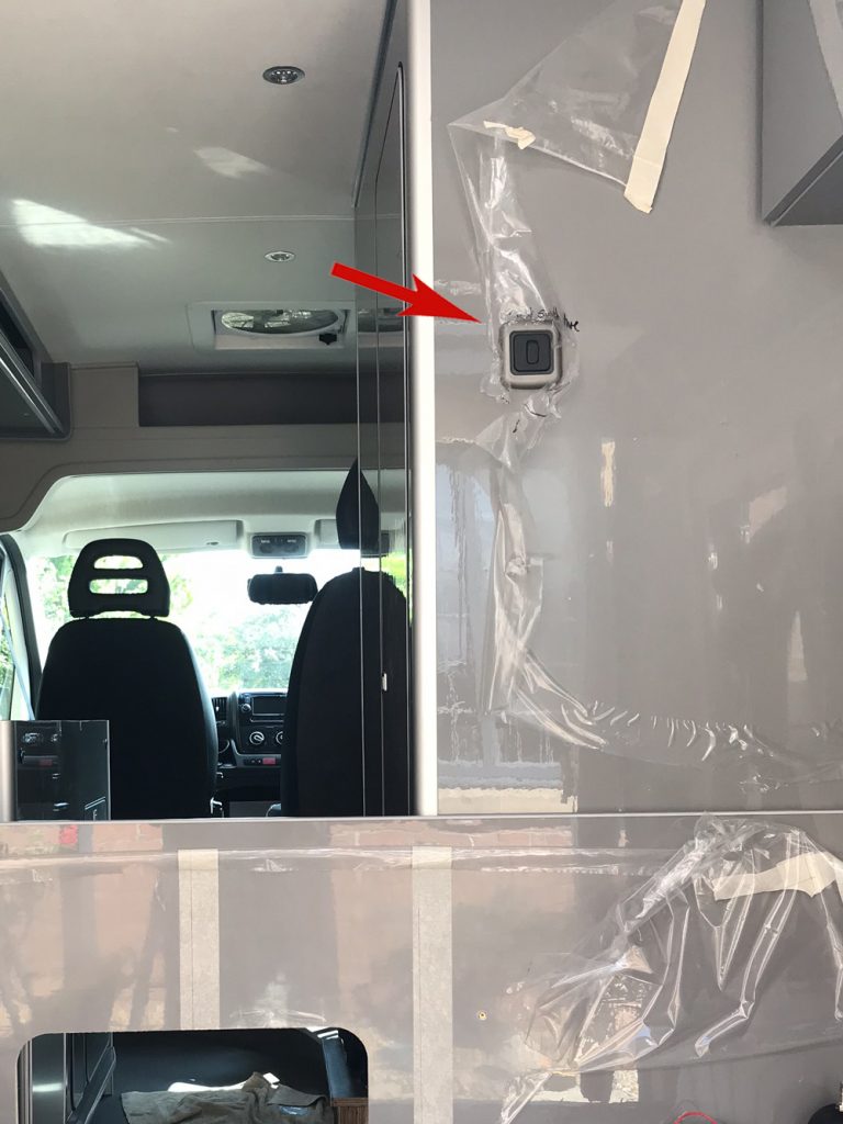
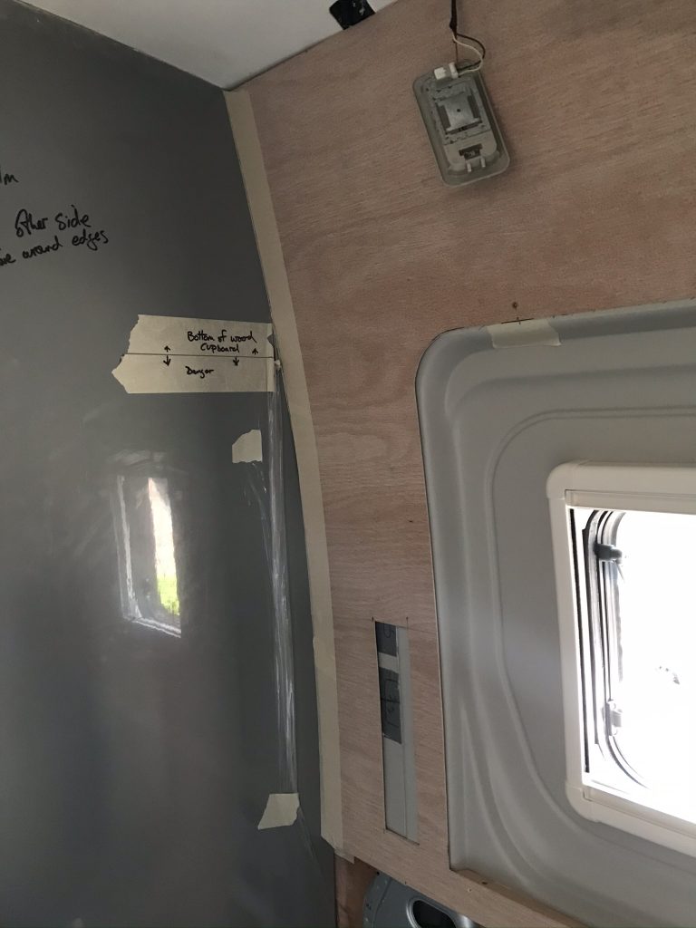
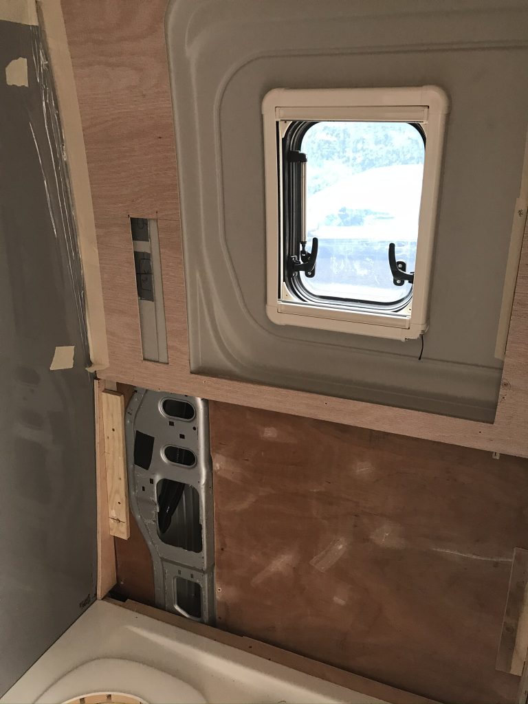
Hidden Cables and Light Switch: I wanted an on/off switch fitting on one of the outside bathroom walls. I selected a position that is easy to reach and located around the side of the bathroom over the bed area as below. However, to fit this it meant I would have to hide the wires inside the wall. To do this is shown in the next image

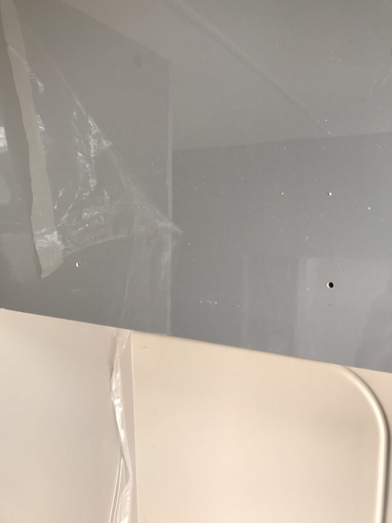
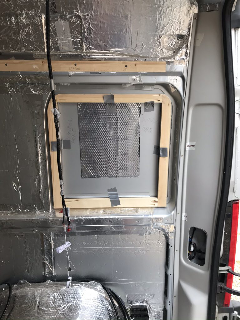
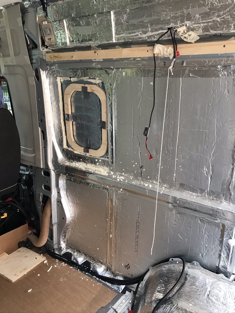
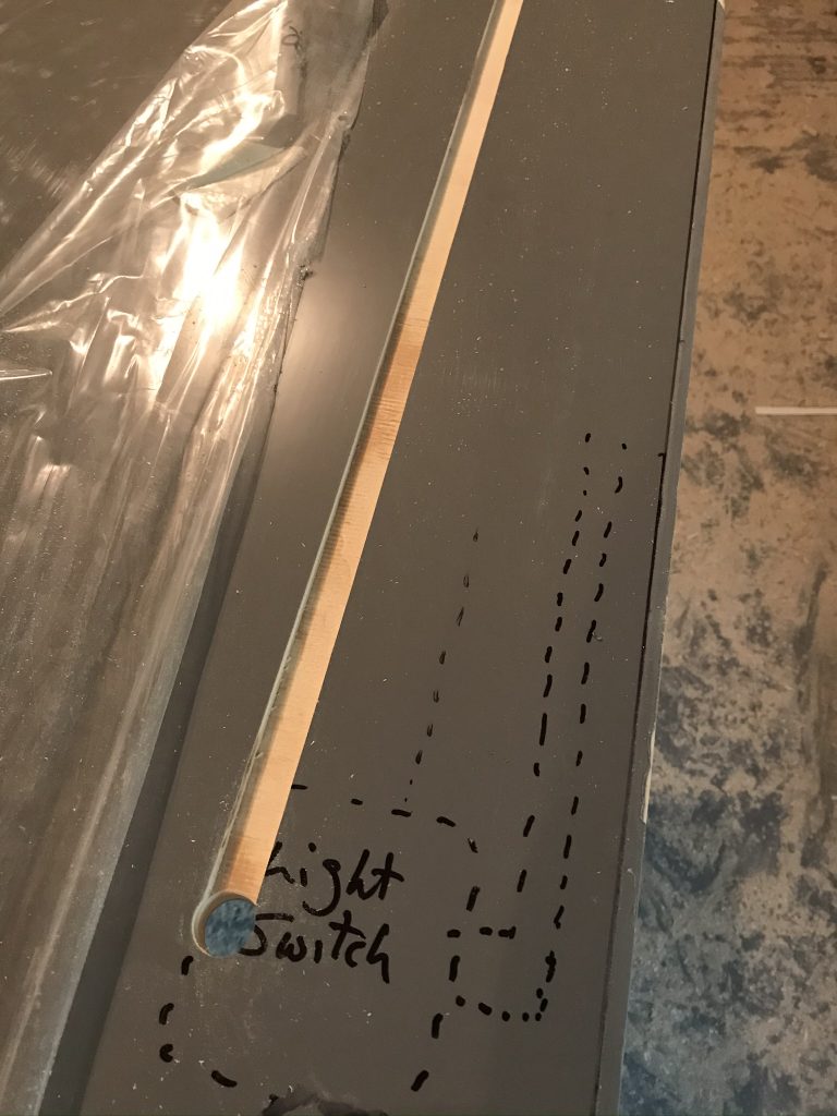
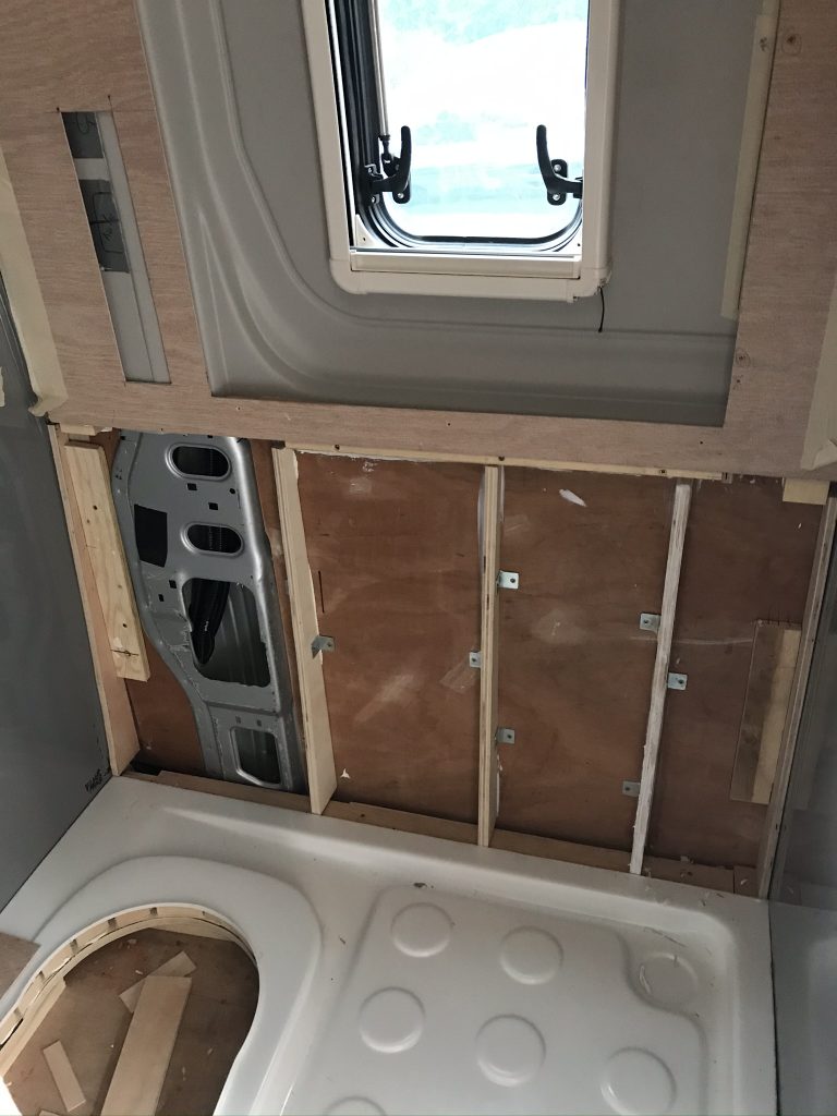
Below: The Side Wall of the Bathroom. This recess (use a router) will hide the light switch on/off wires. The recess will be covered with the Bathroom’s White Panels, thus hiding any wires.

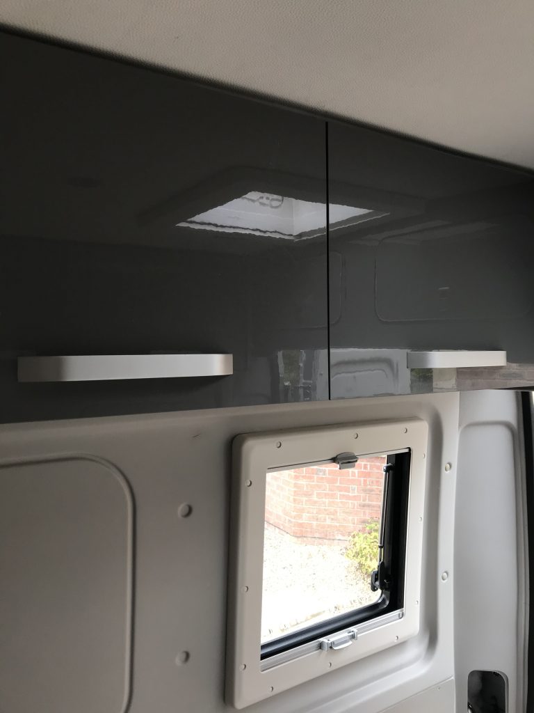
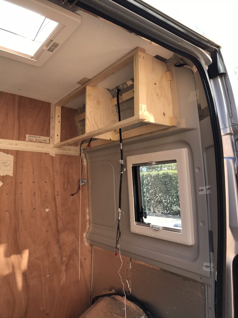
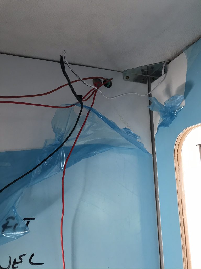
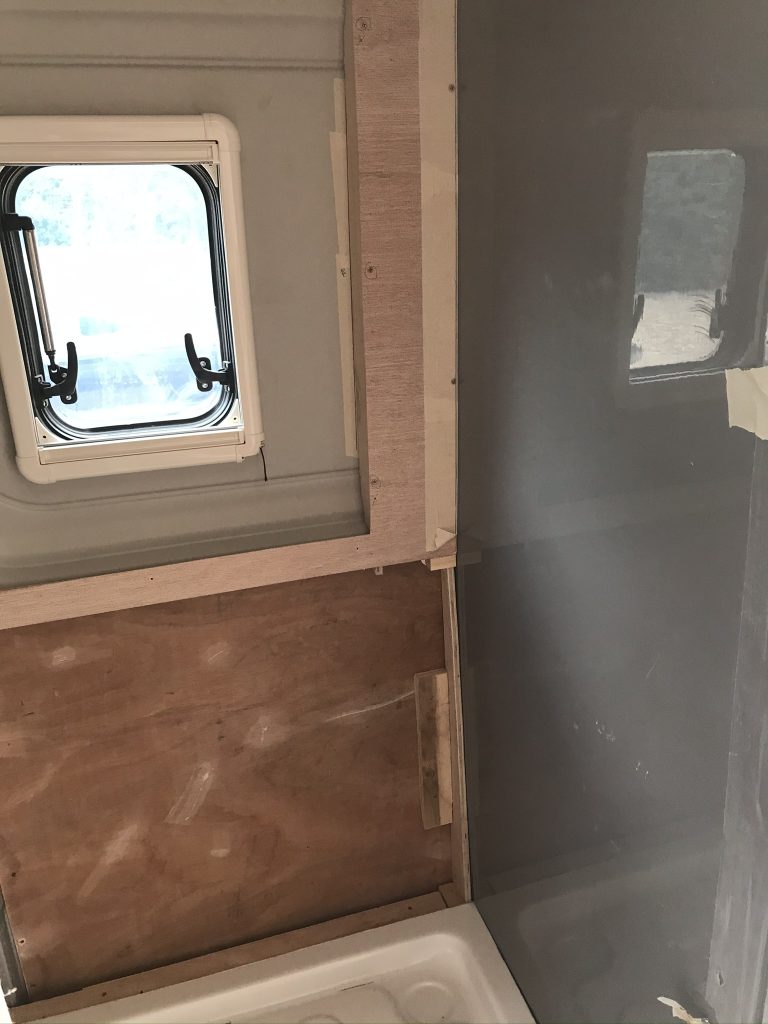
Below: Inside the Bathroom, shows the hidden wires now covered with the white panel. I separate roof panel will be fitted with a light so all the wires will be hidden

Below: The Bathroom roof is fitted and all the wires are now hidden.

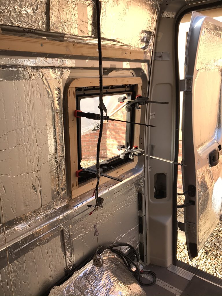
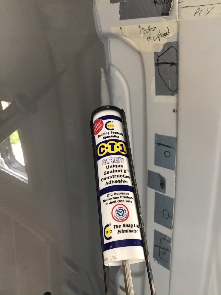
Below: The next job is to make sure that the wet-room walls stay in place and that a gap doesnt appear between the van panels which are flexible. The walls are screwed in place and below I am adding a product called CT1 between wall and panel. CT1 is super strong and flexible, it is stronger than Sikaflex 512 so be careful where you use it, only use it if you never plan to remove or seperate a panel.

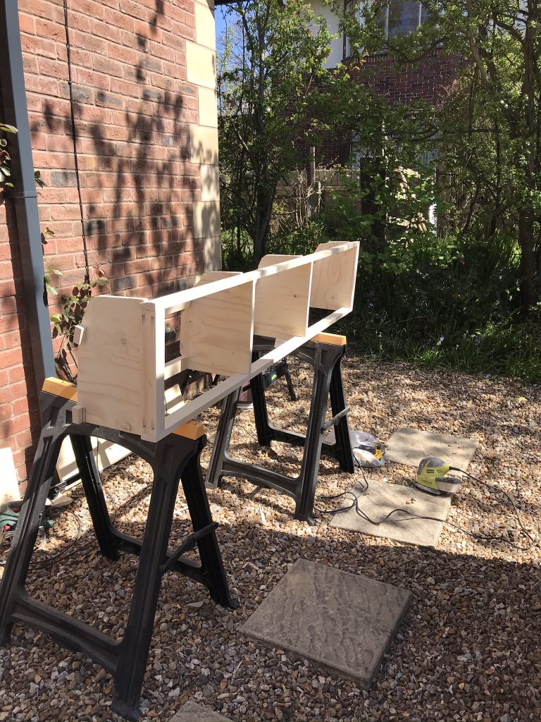
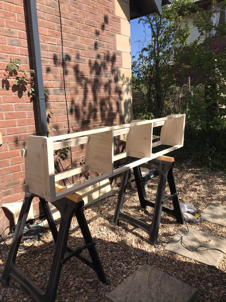
The panel below is curved. Its made out of two sheets of 3mm ply (fairly thin and easy to bend). The first sheet runs horizontal and is fitted to the wall. Then the second sheet is glued to the first but running vertical. This gives the panel a lot of strength plus a solid curve. The wood is then covered with the white plastic sheet or board further adding to its strength. This is not over important but good to have as all walls are less flexible and firm, they are pretty solid when pressed.

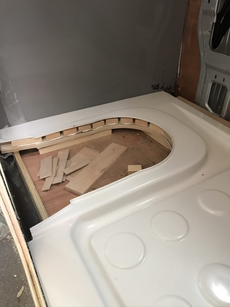
Below: The bathroom floor shower-tray being fitted. I added more wood blocks than shown and then injected foam into the gaps. The reason for this was to make a very firm base. These panels can crack over time and cracking is often due bending. Make sure your base is properly supported and firm, its not something that can easily be replaced without ripping it out.


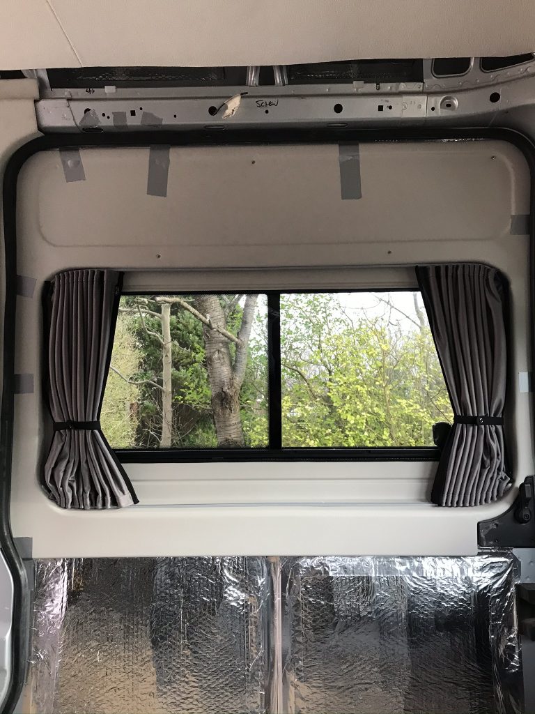
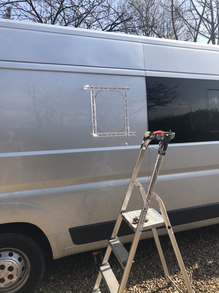
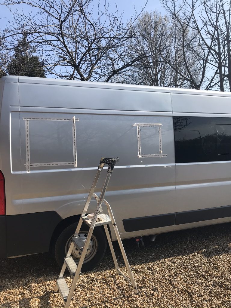
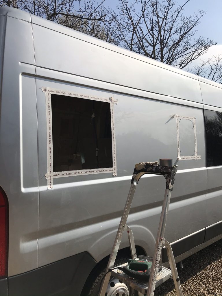
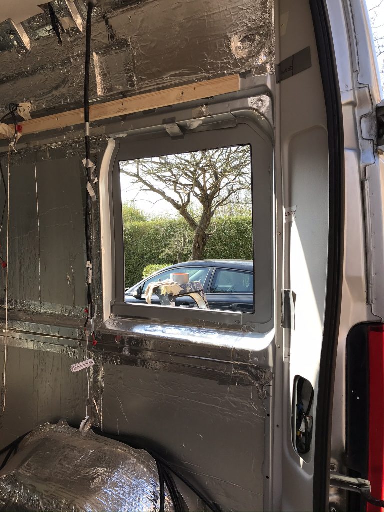
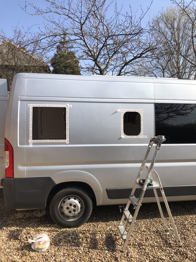
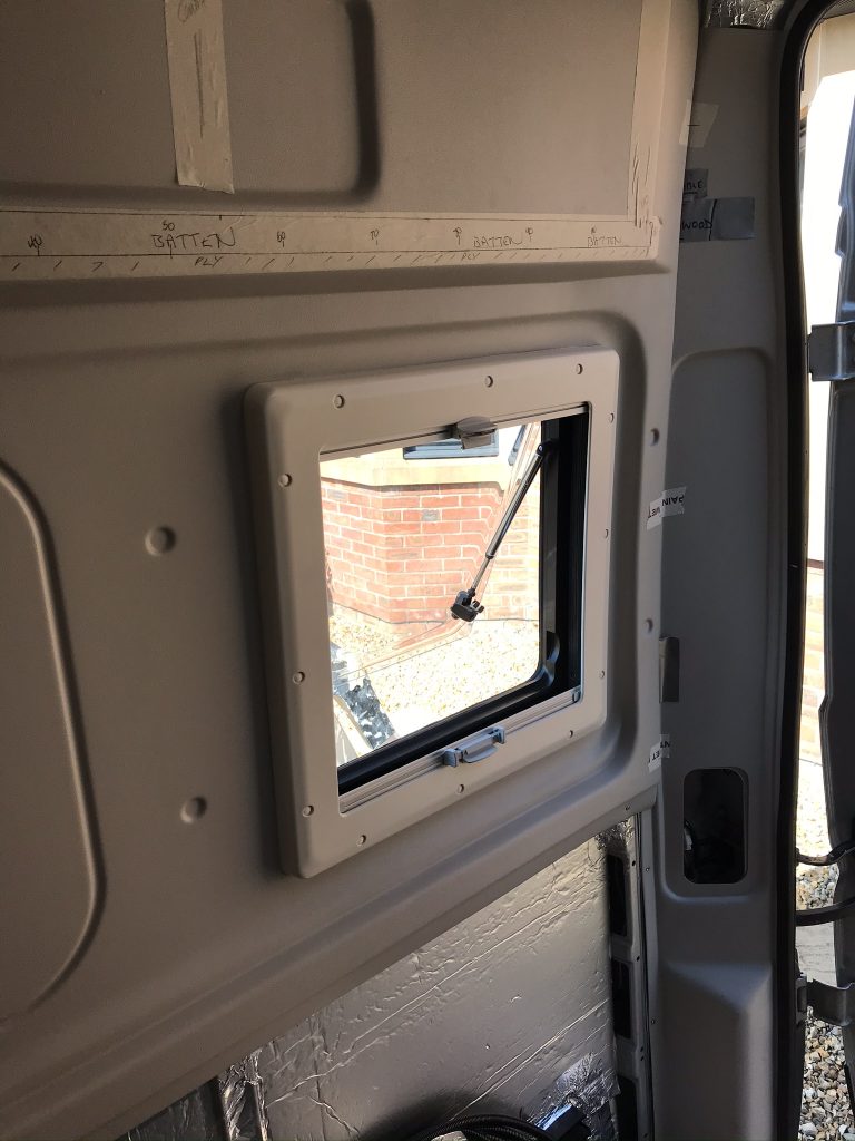
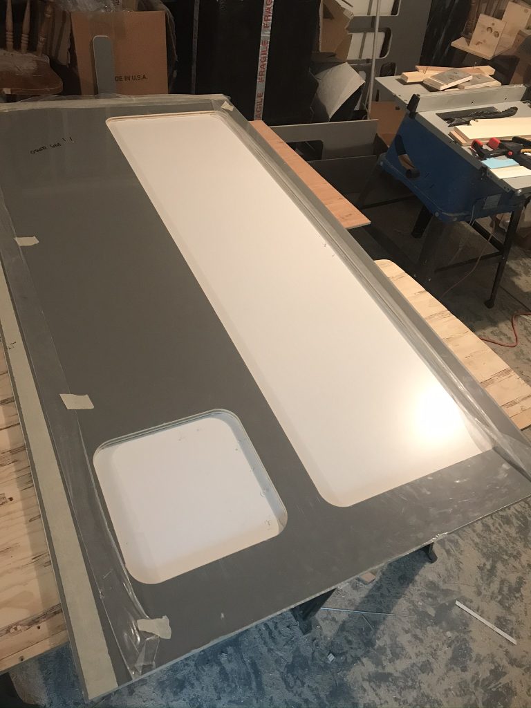
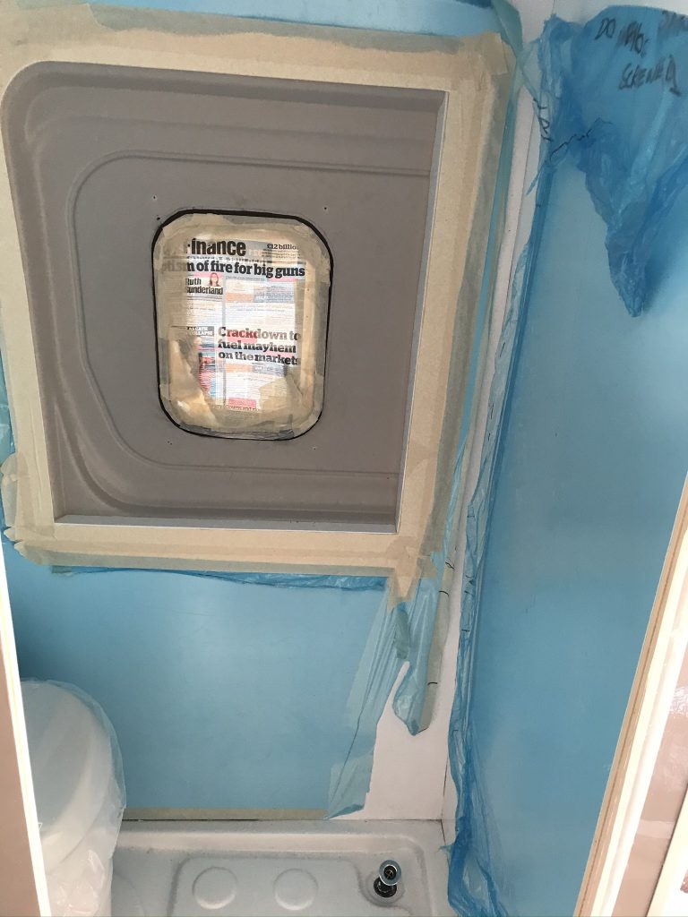
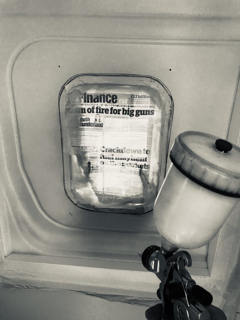
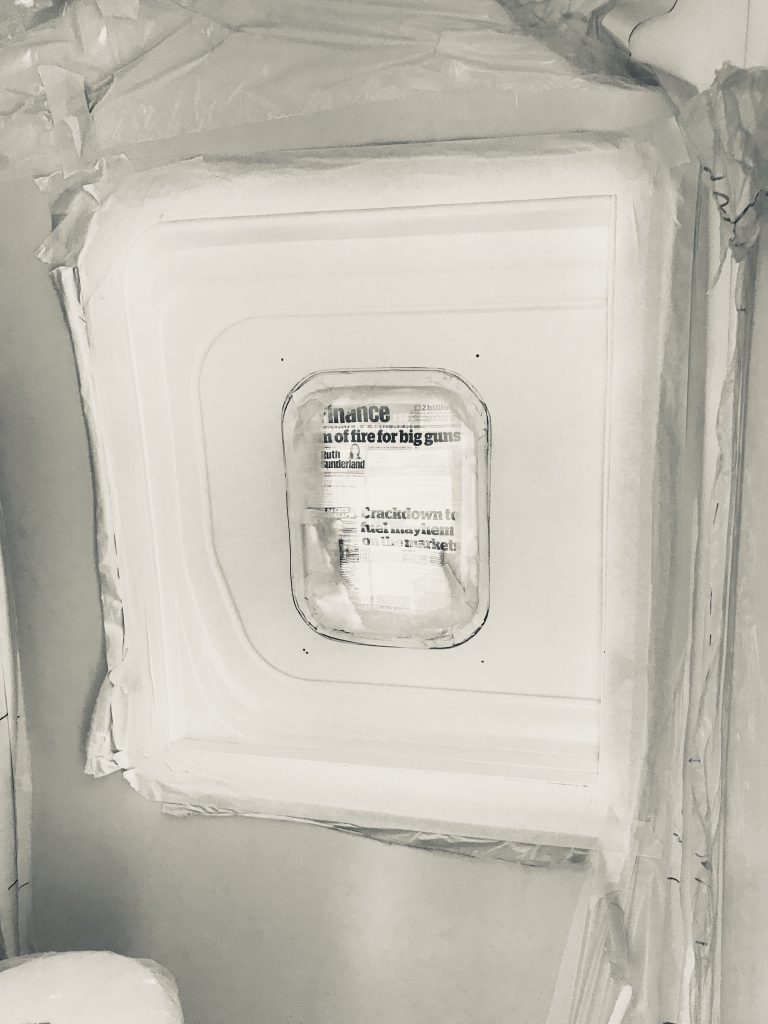
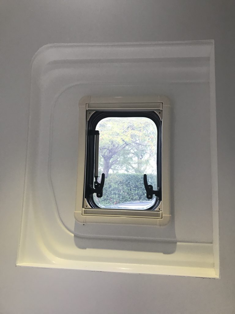
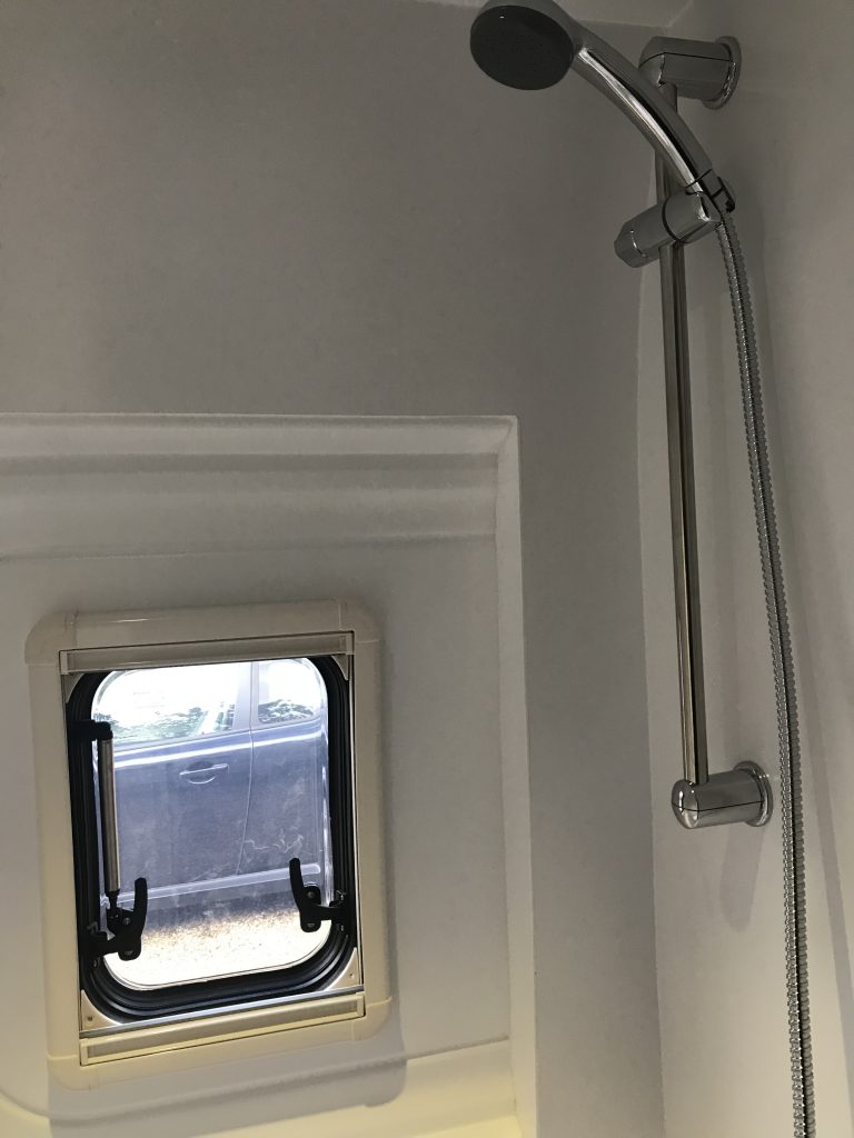
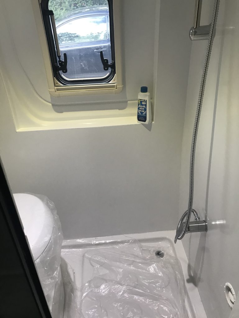
Below: Now that the walls are covered and sealed the only problem is that the walls are bright white and the area around the windows is beige. I could of course leave it as it isn’t too bad. But I want the entire room to be the same colour so below I am masking around the window as I plan to spray it. Before I do, I will explain the type of paint I will use, do not use any paint, you need a special plastic paint. (I will explain further down this article)

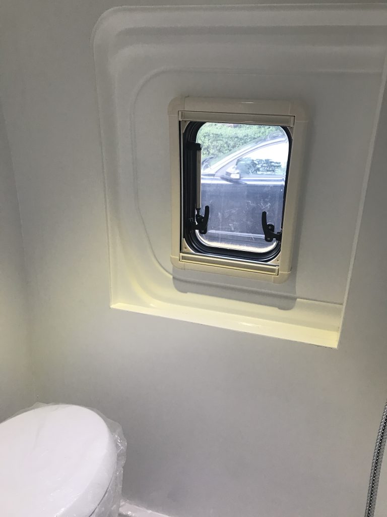
The toilet is fitted and the area around the window is masked ready to be sprayed white using Kolorbond Bright White

www.kolorbond.co.uk/

Technispray Paints Ltd
Catherine Street
Aston
Birmingham
B6 5RS
Email: info@kolorbond.co.uk
Tel: +44 (0)121 326 8020
Fax: +44 (0)121 327 1507

Plastic Paint: Its important to use the correct paint. The paint above is specially formulated for plastic, it wont fade, it wont chip and if you were to spray a thin strip of plastic and tie it into a knot it wont flake or come off. In other words once its on, it stays on. However it costs £40 a litre, it’s not usually available on the high street it’s mainly used by the trade. I managed to buy half a litre.

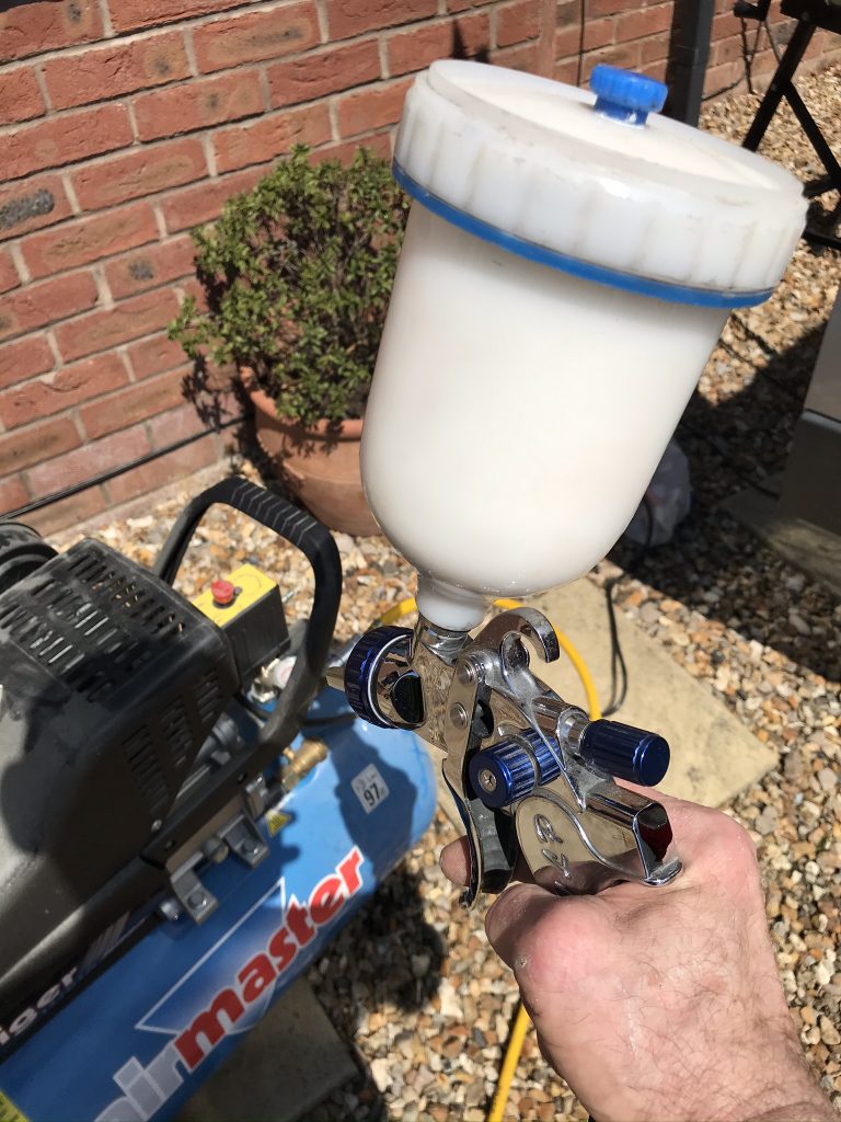
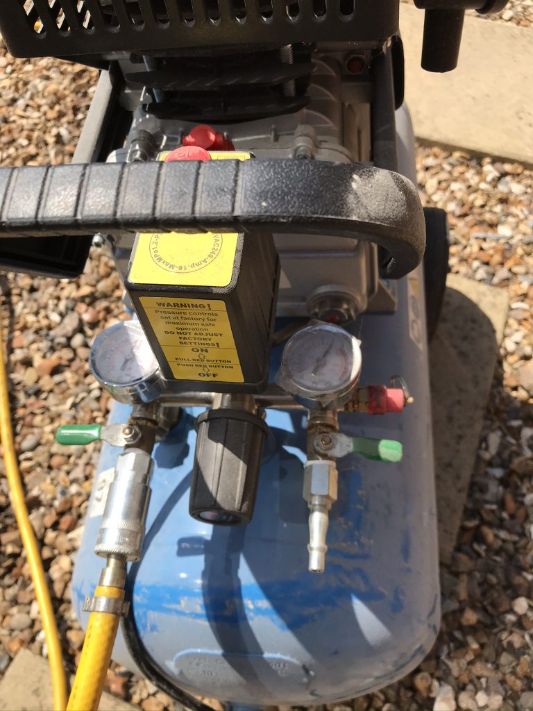
To use, requires a compressor, nothing special, you can spray at 40 psi and the paint comes ready to apply (you dont need to thin it) just make sure you prepare the area well (see the Kolorbond website for details, link above)

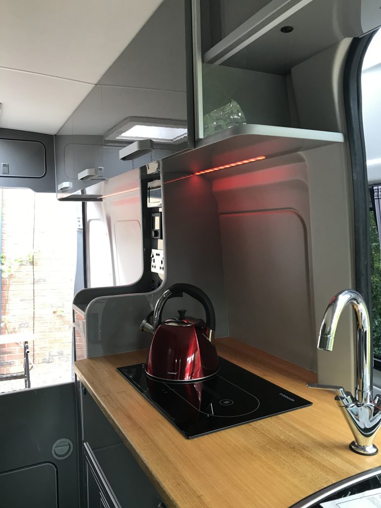
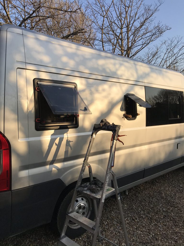
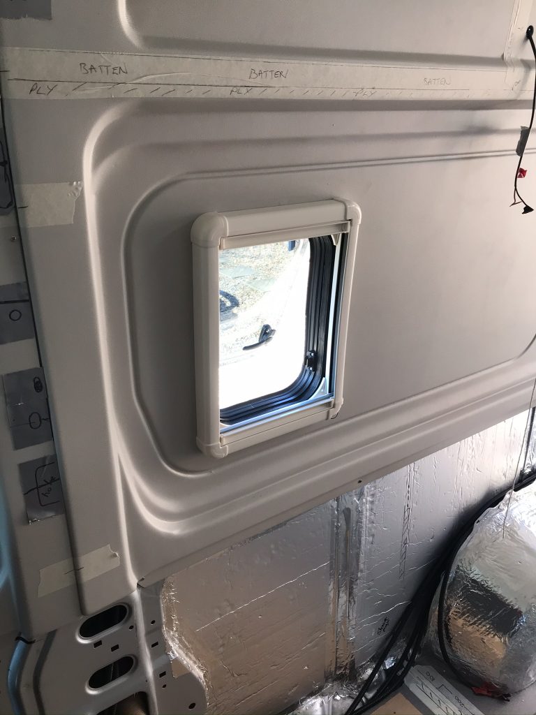
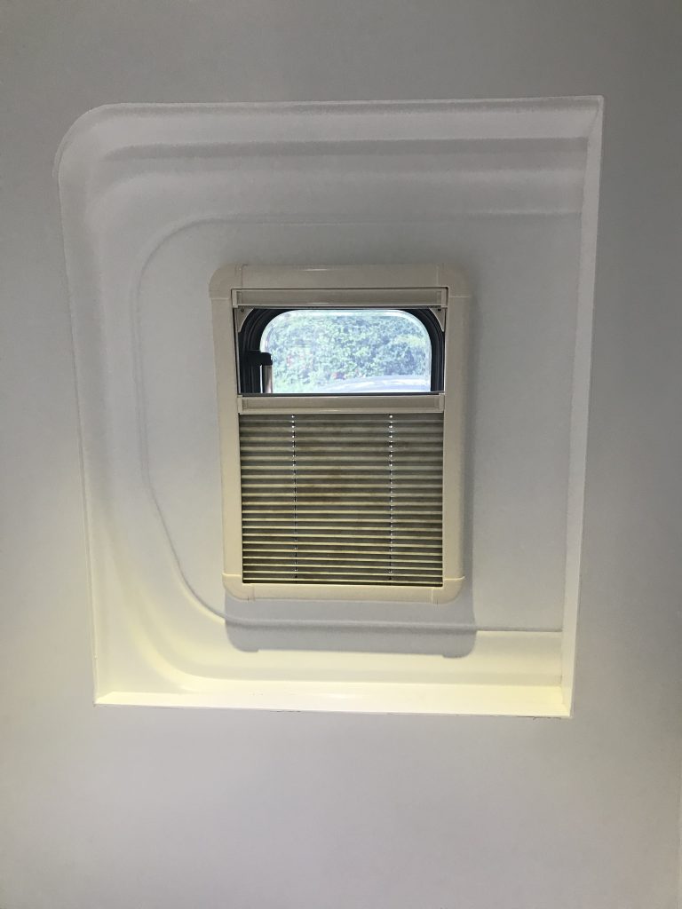
Below: The images aren’t too good but the walls are all the same colour, bright white. A heating vent will later be added so that the room can be used to dry wet clothes.

Below: If you are wondering why I put the shower adjuster so low, it’s because the pipes at the back of the wall would end up on or above the bed. I could have used chrome pipes and raised the adjuster, or bought a plastic panel to cover the pipes (available online). However, I decided I am happy to keep it low.

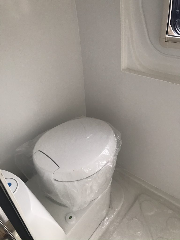
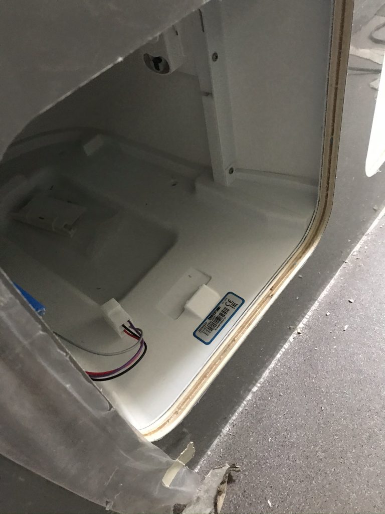
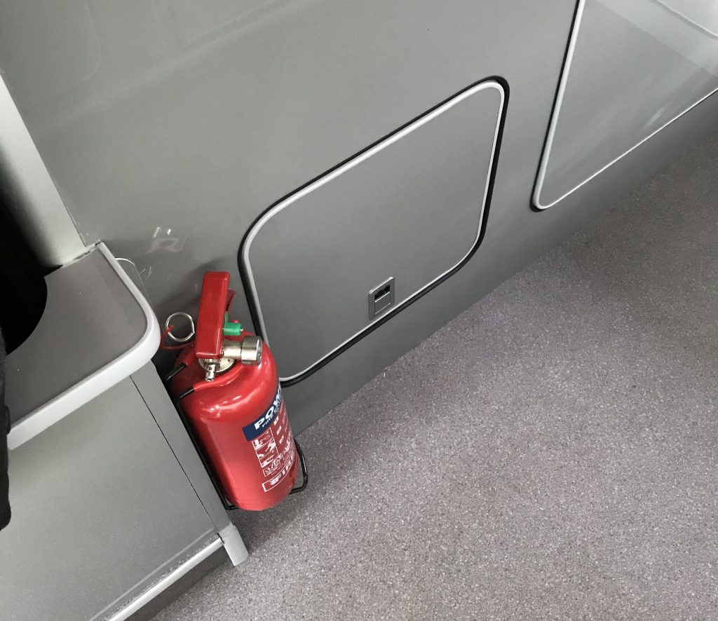
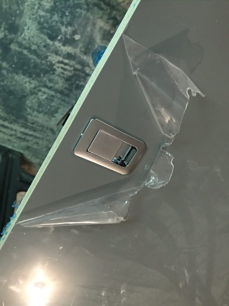
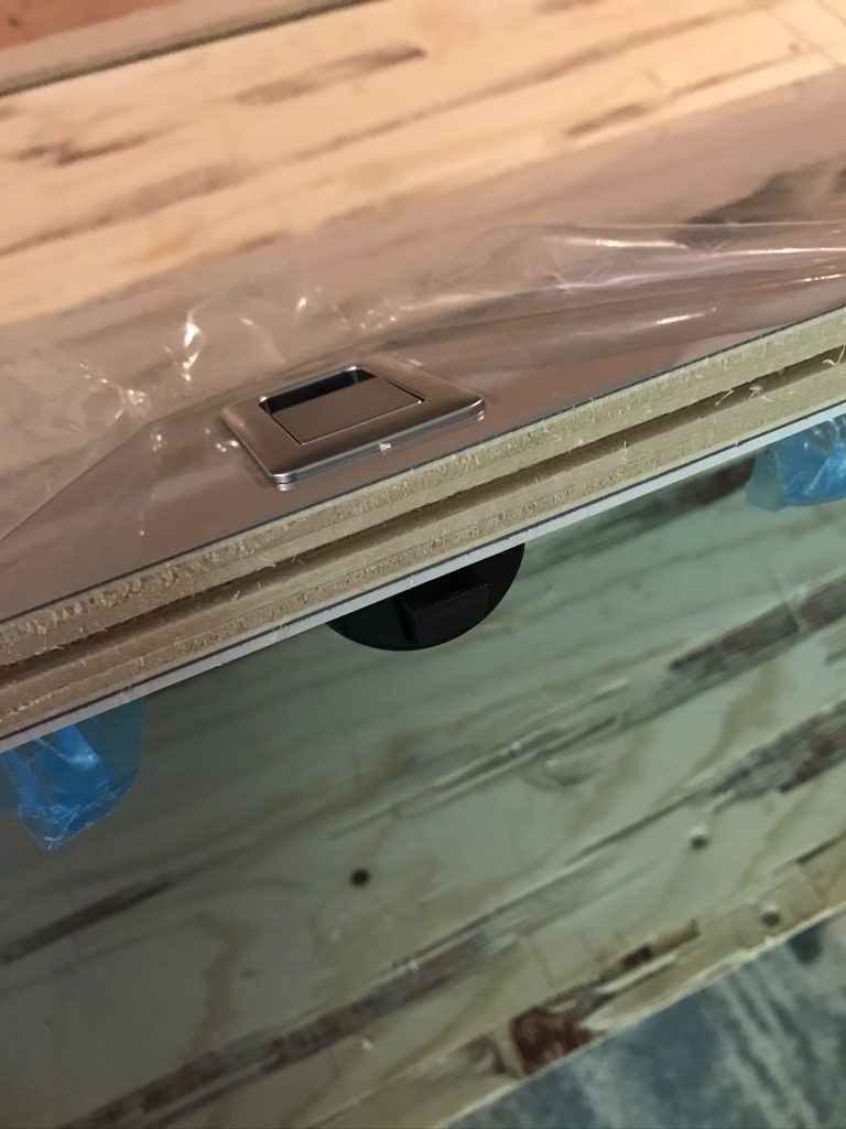
Below: The Thetford Toilet access point. This is now inside the van. I prefer this method to making more holes on the outside. Since fitting I can find no negative points, or any valid reason why it shouldn’t be fitted on the inside of the vehicle.

Furniture – The doors

Once you have your panels cut you will need to finish some of the edges. Whenever I didn’t use the aluminium profiles and had a non-laminated edge I had to used iron-on laminated edging. If properly fitted it’s really solid. I tried removing some to test it using a Stanley Knife blade and it was breaking up before the glue gave in. In other words it was well and truly bonded, which is what you want to see.


Below: Note the Ferrari cap, it’s carefully positioned on the seat to make the readers think I have a Ferrari….cap. I don’t know were I got that cap from, it’s not something I would buy, maybe someone threw it at me in anger?

Below: As I have a few door handles to fit I decided to make a template. Which not only saved me a lot of time but ensured that each handle was perfectly aligned.

Veneers Online Ltd, 34 The Avenue, Gainsborough, Lincolnshire, DN21 1EW, United Kingdom.

https://www.ebay.co.uk/itm/Iron-on-Pre-Glued-Veneer-Melamine-Edging-Tape-22mm-DUST-GREY-GLOSS/264516801960?var=564233656537&hash=item3d966e15a8:g:-KwAAOSwDyRdupIA

High Gloss Grey Panels

I decided on high gloss grey panels as grey is a fairly fashionable colour at the moment (2020), its also a neutral colour meaning any colour will go with it and….it has no markings or patterns its also easy to match with aftermarket edging. What I found with the Grey laminate (its actually called Dust Grey) is that there is a perfectly matching iron-on laminate edging thats easy to buy and fit. I also planned to use some aluminium on the interior and thus the grey should work well together, well thats the plan, I wont know until I try it.

Below: The Dust Grey 15mm Lightweight Ply Board with matching iron-on edging strip. Both came from completely different suppliers. As you can see they are a perfect match.

Veneers Online Ltd, 34 The Avenue, Gainsborough, Lincolnshire, DN21 1EW, United Kingdom.

https://www.ebay.co.uk/itm/Iron-on-Pre-Glued-Veneer-Melamine-Edging-Tape-22mm-DUST-GREY-GLOSS/264516801960?var=564233656537&hash=item3d966e15a8:g:-KwAAOSwDyRdupIA

First a word about boards and suppliers. It took 10 sheets of Lightweight ply to build all the furniture in this vehicle. Dont be tempted to use MDF, the weight difference is considerable, your van weight will increase significantly, overall you will use more fuel carrying it around every time you go out. 15mm Lightweight Ply is not cheap, good quality 8 X 4 Panels cost between £70 and £180 a panel depending on whether you buy double sided, the type of finish or the type of laminate.

Moreland Lightweight Ply https://shop.morlanduk.com/

Suppliers: Shop around, there arent many selling this type of ply. So select a company that gives its full address online and an office phone number. Be cautious of companies that only list their mobile number, if you have a problem they will likely avoid your call, some only answer when it suits them, not you.

Your Time Not Theirs: Plan carefully when you will need your ply, you will need to order in advance. Make sure you get a firm delivery date and a company that will stand by a date they provide. Shipping can be expensive you want to make sure you pay for a single trip if possible. (a supplier will charge £80 to £110 to ship a single 8 X 4 Sheet). If they cannot deliver on time, or are very vague, walk away. You may be able to do other jobs whilst waiting for your ply but eventually not having the materials can really mess-up your plans. It could mean your vehicle is not ready for a summer holiday. You have a lot of work to do after the ply is fitted so take note of this advice and get a firm date.

Below: having used my templates to cut the bathroom wall panels to size you can see below I then added aluminium edging. A word of caution about aluminium edging….. often it doesn’t fit the board or the boards dont fit in it….Yes, its listed as 15mm and the boards are listed as 15mm but in reality this isn’t possible. Bare Plywood boards are indeed 15mm but when you add the laminate this can become as much as 17.5mm overall (even higher). The aluminium may be listed as 15mm but its supposed to have a gap of 16mm. If your board is 15mm bare and the laminate is 1mm either side then the board will be 17mm minimum. Some laminates are thicker than others, some vehicle builders use special aluminium profiles that allow for thicker boards (17mm profiles not easily attainable). You may need to use a router to skim some of the laminate off the board in order to get them to fit the profiles, something that most suppliers omit telling you. I had to do this, my panels were not even close to fitting. However, a quick skim with a router and they slotted in nicely. Talk with your supplier, Moreland Ply for example do use a thinner laminate so ask around before you buy.

Morland Ply,
Unit 2, Buttington Cross Enterprise Park
Welshpool
Powys
SY21 8SL

Tel +44 (0)1938 551 980

Below: Preparing to reduce the thickness of the laminate at the edge so that the panel will press firmly into the aluminium profile.

Below: The Router cutter

Below: This is the underside of the cupboard. I am using a router (same cutting tool as shown above) to cut slots into the panel. These slots will be used to hold the aluminium lighting strips.

Below: A change of cutting tool. This is for the Knock-On Edging strips (T Trim) that run around the edge of some of the panels.

T Trim (Knock-On Trim)

Available from Clearcut Camper Design

28-29 Hele Manor Business Park,
Roundswell,
Barnstaple,
EX31 3UL
Phone: 01271 373853

Master Templates

This Peugeot Boxer camper-van used 10 sheets of 15mm Lightweight Ply its hard to see where it all went but I was left with hardly any waste. Lightweight Ply isn’t cheap, at £150 a sheet (many cost more) then you dont want to be making too many errors. To avoid unnecessary errors and wastage I recommend making templates. In fact I made a template for every piece of furniture in this vehicle. It took a lot of extra time but it was worth the time spent. A template will allow you to check the fit and also let you see what the finished result is like. On occasion I made changes and was so glad I didn’t use the 15mm ply without checking first.

Below: I am making the side of the wet-room wall out of some used boards that were scrap (or for use elsewhere). I started by making a cardboard profile then cutting the wood. The shape is not easy to get right as the plastic panels are a complicated shape. Often van builders wont try to follow the exact profile, there is a rubber edging product that sits between the wall and side of the van. I didn’t want to do this, instead I wanted my panels to form the exact profile. Below I will show you a way to do this.

Below: look carefully at the edge of the wood notice the yellow areas? I’ll explain what this is in a moment. The problem with plastic panels is that they may not be rock solid with fitted. This means when you press against them they can bend. I needed a way to prevent gaps appearing between the plastic panels and the wall panels I am making. I explain this in better detail in another post but for now I will explain what the yellow patches are. Firstly I cut the wood panel as close as I could, however, as much as I tried it wasn’t totally perfect. To get it perfect I stuck a layer of masking tape onto the wall and applied grease to the tape. Next I placed my wood panel against the plastic wall panel and filled any imperfections with wood filler. In short I made an exact profile of the plastic panel onto my wood panel. I now had an accurate template I could work from.

Below: I almost made the entire wet-room as a mock-up. This was a good idea as it allowed me to position it and make sure my drainage holes were located in the right position and not over a cross-member in the chassis. It also gave me an idea of what it would look like and how much space I have available.

Below: You cannot use a spirit level in a van. I made my own 90 degree straight edge to make sure the panels aligned correctly.

Solway Wall Panels

What do you cover the internal walls with? Thats a question everyone building a camper-van will have to decide and the first choice for most is camper-van carpet lining or 4 way stretch lining. The reason this is often used is because its very easy to fit especially around difficult angles as its forgiving and stretches in all directions. Its also low cost and it looks good. The next choice is usually wood. Wood is a liitle more difficult to fit but again it does look good if properly fitted.

My Choice and Why: Because I planned to use a laminated light weight grey ply (15mm thick) I ruled out using wood wall panels. The next choice would be to use stretch fabric and whilst it looks ok it can be found in almost every homemade camper-van and I wondered whether it may have been around a little too long and will soon go out of fashion, who knows? In the end I took the more expensive option and bought a full set of Solway Panels (links to Solway Panels are at the bottom of this page). These are molded plastic panels that are very easy to maintain (wipe down). They are fairly easy to fit and give a professional finish.

Price: The price for a full set is around £1,100. I later added the rear wheel covers as well so that pushed the total to £1200. Not cheap, but having owned them for over six months now I can honestly say that I am glad I decided to use them.

Below: The panels arrived long before the van had been prepared or even insulated. I wanted to see how they fit before insulating the van. I didn’t want a situation whereby the insulation I added was so thick that the panels wouldn’t fit.

Below: The panels are fairly close but they do need a little shaping and cut-outs here and there.

Below: The window panels needs to be cut. Its worth a mention that unlike Stretch Fabric or Wood Panels you have one attempt to get it right otherwise you end up with a costly mistake. Take your time, measure twice, cut once. Fortunately, I didn’t have any costly errors.

Below: It probably seems an odd time to fit the curtains long before the van is completed but I wanted easy access behind the panel so I fitted them the same time as I fitted the panels (and managed to keep them clean throughout the build).

Internal and External Window Cutting: Now the difficult part. I wanted my internal windows to align neatly with the internal wall panels, I also wanted the windows to align correctly outside. Get one of these cuts wrong and you end up with something thats out of alignment and looks a mess. This is why these external windows (shown below) were not fitted when I installed the other windows.

Firstly mark out where you want the internal windows on the plastic panel, make sure there are no supporting metal van struts behind and no metal seams on the outside of the vehicle, you dont want to cut through one of these seams. Also make sure that the window area on the inside and outside of the van are in a neat location. You wont know if you are right until you start cutting so heres what to do. Drill a small hole (1mm) through the plastic panel so that it “marks” but doesn’t cut through the vans metal wall. Remove the panels and check the location of the “mark“. If its wrong then you can stop, the only damage would be a small 1mm hole. Try and work out were this drill mark is on the outside of the van and make sure the outside window is where you want it. Dont start cutting metal just yet.

Below: I have drilled my guide hole then cut out the window square in the panel. If you look carefully you will see I have made a wooden frame to support the window. Both the bedroom and bathroom windows have been cut. Now that these are cut I can draw around the wood frame and prepare to cut the van metal. The windows should now align correctly just make sure your cuts are straight and not at a slight angle.

Below: this image shows the wooden frame that sits under the plastic wall panel. The external and internal window sections will screw into this panel. Use the panel to locate exactly were you will cut the hole

Below is a link to Kiravans suppliers of stretch wall lining

Solway Panels: https://solwaycamperconversions.co.uk/online-shop

Selecting an Inverter

An inverter is a device that connects to a 12 or 24volt supply and converts it into 240 volt energy. There are many devices on the market and prices vary tremendously.

Which Type to buy? As a rule its usually wise to calculate what you think you need and add a bit more. If you are planning to charge laptops, cameras, run TV’s etc then you may need something like a 2000 watt inverter. But what if you are not planning on using a lot of energy? I personally don’t want to load my van with a lot of power hungry devices. Many people are the same, but give a thought to how much power the inverter will use on stand-by or start-up mode because a 2000 watt inverter may use more energy than an 800 watt inverter even before anything is plugged in. The amount may not be excessive but remember all these little drains on your electrical system do add up.

Pure Sinewave or Modified Sinewave? Without going into great detail check the applications you wish to charge. Many have bought inverters that are not Pure Sinewave and they work fine until they attempt to charge applications like the iPhone. You may find it will start to charge for around a minute then stop. Some applications require Pure Sinewave only, others are not so fussy. Below I will list a description for a Modified Sinewave Inverter that will charge the iPhone (it’s also a good price).

Victron or Krieger? The Krieger KR2000 1000W or 2000W Power Inverters (They go even higher) offer the best value for money in my opinion. They have good internet feedback and they are capable of charging most iPhone and laptops that I know of, (at the time of writing this article). Costing £160 (around $200) for the 2000W version, it’s value for money. So why didn’t I buy it? I decided on the Victron 12/800, it cost more than double the price and delivers only 800 watt as opposed to the Krieger’s 1000 watt. I didn’t require anything above 1000 watt and whilst the Krieger seems to cope with most iPhones (and similar) I did wonder if the day would come that some devices may only accept Pure Sinewave and nothing else. One other point, I am informed that the Victron has excellent built-in protection devices (I am not saying the Krieger hasn’t). The Victron has a proven track record for being reliable and on a very hot sunny day with the Victron stored under my seat (low ventilation) I wanted something that is very well protected. There is also a Eco Mode feature that uses less power plus the ability to add a remote On/Off switch meaning I don’t need to go under any seat to turn it off. Unfortunately Victron charge extra for the on/off remote panel whilst the Krieger Inverter comes with the panel included in their price.

Below: The Kreiger 2000 Watt Inverter

Below: The Victron Phoenix Bluepower 12/800 12V 800W Pure Sinewave Inverter

Reliable and Efficient

The Victron Phoenix Inverter is short circuit proof and provides protection against overheating even if there is a high ambient temperature or an overload occurs, while having a full bridge plus toroidal transformer.

Economic Functionality

With the possibility of an Eco mode the Victron Phoenix Inverter will automatically switch to standby if the load decreases and gets lower than the pre-set value of 15w. Once the inverter is within standby mode the inverter will then switch on for a short time if the load then increases above the pre-set level and it will stay on.

Remote Monitoring

The Victron Energy Phoenix Inverter VE.Direct is Bluetooth compatible and can be controlled and checked on a smartphone, tablet or laptop via a Bluetooth Smart Dongle.

All settings of the Phoenix Inverter can be configured with the VictronConnect app.

Electrics P5 (Completed)

If you have jumped to this page and haven’t seen the various stages of installing the electrics and would like to see them, then follow the menu “Flux Converter” Parts 1, 2, 3 and 4.

The Electrics are now installed and I have added some polished aluminium plates to the area around the Flux Converter Box which I made from a sheet of aluminium.

Everything is working fine. The engine provides charging power via the 60 amp Sterling Battery to Battery Charger and the Solar provides constant power from the roof on a sunny day. If the batteries are full and I switch on an application, then I have a very good monitor called the Juntek VAT 1100 that shows me the power being consumed. Its works via a Shunt on the negative battery terminals and measures the power being used (as well as other things). The Juntek is not expensive to buy (around $30) and its fantastic value for money, its also has a very good rating (google for yourselves).

With full batteries the intelligent Victron MPPT Solor controller knows when the batteries are full. As soon as I switch on an application which starts to consume energy from the battery then the Victron Solar Controller detects this and increases the watt/amps to compensate for the power being consumed. I need a sunny day of course but basically the system knows when power is being taken from the batteries and immediately replaces it via the solar panel.

LifePo4 100Ah Battery with BMS and Bluetooth

LifePo4 Battery Monitoring using the Bluetooth App

Removing the CBE Split Charge Relay.

What does this mean? The CBE Control unit has a built-in Split Charge Rely or Voltage Sensitive Relay. In short this takes power from the vehicle alternator and sends it to the Leisure battery. Nowadays there are more sophisticated chargers, like the Sterling Battery to Battery charger and its this type of charger that I want to use on my camper van. The Sterling Battery to Battery Charger is designed to operate with all types of batteries, it works well with the Euro 5/6 Engines which deliver high voltages when the vehicle de-accelerates (when you take your foot off the gas peddle). Most chargers of this type deliver up to 30 amp of charge, Sterling also make this type. However, the the type I am fitting can deliver up to a 60 amp charge without causing any damage to the battery.

First I need to bypass or stop the CBE Voltage Sensitive Relay from working.

Look for the resistor marked R37 this is the resistor you need to disconnect. Its quite simple to do.

Below: take a sharp set of wire cutters (I bought a new pair just for this task) and cut through R37. Be careful NOT to cut into the circuitboard.

Below: look carefully and you can see R37 is now disabled (or disconnected).

Below: a better view of the disabled resistor.

Below: I have added a small section of Heat Shrink, I plan to insulate the end of this resistor so it can never make any kind of connection (just to be safe).

Below: adding some heat from a Hot Air Gun.

Below: The task is completed. Its worth pointing out that whilst the CBE will not charge the batteries via the Voltage Sensitive Relay (now disconnected) the LED Display Monitor will still show the Battery Levels and the Mains Charger will still work and display as normal. All other functions will be displayed and work as normal.

Power via the van ignition.

This section shows how to wire a device via the vehicles ignition feed. This applies to the Peugeot Boxer (shown) Fiat Ducato, and Citroen Relay. The vehicle I am working on is a 2016 Peugeot Boxer.

What applications do I need to connect to the Ignition Feed? Firstly you dont have to connect anything, the choice is yours, some people do, some people dont. I will connect two units A) The Sterling Battery to Battery Charger and B) The CBE Control Panel. The reason I prefer to connect to the ignition feed is because I rather these units shut down when the engine is off. The CBE unit is quite intelligent, it understands when the engine is off or on via the ignition feed and thus things like the refrigerator will remain switched on.

Below: Remove the panel near the steering column

Below: Look for the main ignition cable and remove the black insulation to expose the wires

Below: The ignition feed on the Peugeot Boxer or I believe Fiat Ducato and Citroen Relay is shown below. This wire is White with a Black Line it may also be a little thicker than some of the others. Split this wire open with a sharp blade (make sure the ignition is off). Then separate the strands of copper (dont break them) and hook a new wire to them. Next solder the new wire to the ignition feed and insulate with tape. You should have a new wire running from the ignition feed that you can connect to the terminal on the Sterling Battery to Battery Charger.

Below: I am running the new red wire under the panels into the back of the vehicle. It will be totally hidden.

Below: Shows the Ignition feed (Red Wire) that is about to plug into the Sterling Battery to Battery Charge. Different Sterling Chargers may have different locations for this wire. On my unit I removed the “Wire Bridge” which ran across two connections, I’ll call them top and bottom connectors, I connected the Red Wire to the top connector (but check with Sterling Power as your model maybe different).